


14
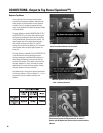
Audio Connections
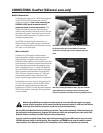
Audio inputs can be connected to the XLR inputs OR the
DataPort connections (QSControl users). This section
provides information on using the XLR Inputs, For DataPort
information see page 17.
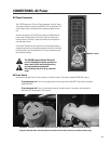
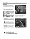
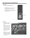
CONNECTIONS- Audio Connections: XLR Inputs
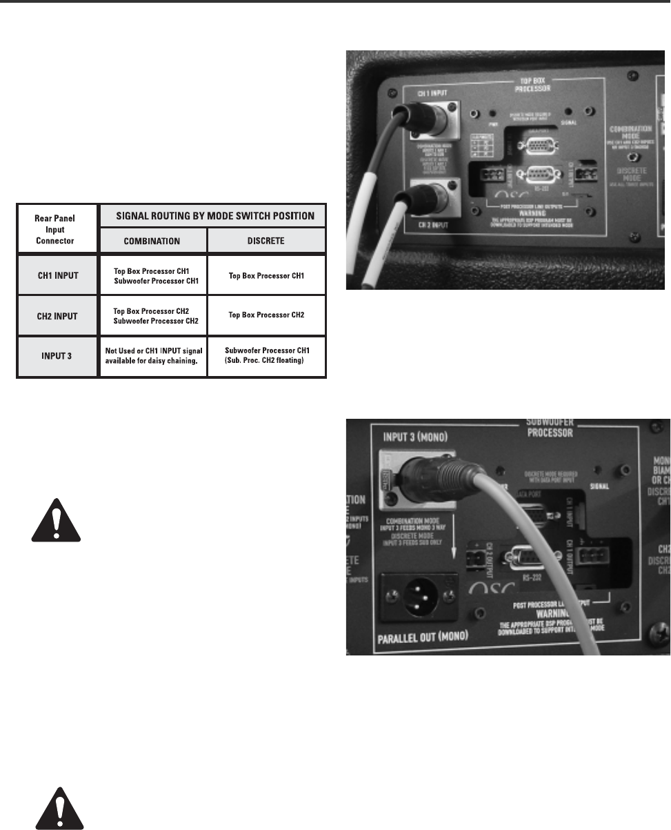
CH1 and CH2 INPUT - In Combination Mode, use these for
2-channel inputs. For mono input, use Input 3 and leave
CH1 and CH2 inputs unused. In Discrete Mode, CH1 and
CH2 Input feed the Top Box Processor only.
INPUT 3- In Combination Mode, Input 3 is used for mono 3-
way input to both processors. In Discrete Mode, Input 3 is
used for the subwoofer only.
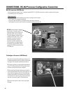
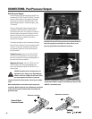
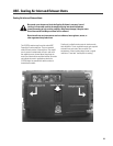
XLR Inputs
If you are using the DataPort connections for supplying audio to
the 215PCM, do not use the XLR inputs.
If you are using the XLR inputs for supplying audio to the
215PCM, do not use the DataPort connections to supply audio.
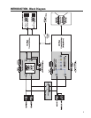
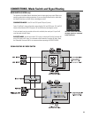
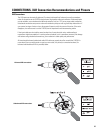
The position of the Mode Switch determines how the input
signals are routed. Select your operating mode before
making connections. See page 7, Block Diagram.
COMBINATION MODE– CH1 and CH2 INPUT are routed
to the Top Box and Subwoofer Processor’s IN1 and IN2
blocks. Alternately, if using a mono input, INPUT 3 is routed
to both Processor’s IN1 block. COMBINATION MODE.
Important Note!
In Combination Mode, CH1
INPUT and INPUT 3 are connected in parallel
(see diagram, previous page. This is why it is
necessary to use CH1 and CH2 Inputs OR Input
3. If all three inputs are used while operating in Combina-
tion Mode, unpredictable results may occur.
DISCRETE MODE– CH1 and CH2 Inputs are routed to the
Top Box Processors only and are in no way connected to the
Subwoofer Processor. INPUT 3 is now routed to the
Subwoofer Processor IN1. Note, the Subwoofer Processor
IN2 block has no input signal connected when operating in
Discrete Mode.