


Part 9
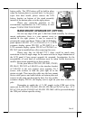
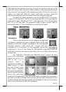
battery cable. The UPS battery will be held in place
when the bottom plate is screwed back. As for gen 6
super slim base model, please remove the UPS
battery bracket on bottom of the stand assembly
instead of the bottom plate as in the right picture.
Please pay particular attention to the
environment requirements for UPS battery in next
chapter “USING THE TOUCH POS”.
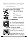
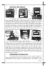
BASE MOUNT UPGRADE KIT (OPTION)
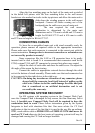
On rear top edge of the gen 5 slim base stand assembly for desktop
mount application, there is a rear connect cover as
marked in the right picture. It can be removed by
pressing the center part down. Either a 2nd LCD display
panel option LM-6101 (12”) or LM-6301 (15”) a VFD
customer display option PD-2501 or PD-2602/U or a
LCD customer display option PD-305 or PD-306/U or
PD-7622 can be installed here after removing this cover.
Please note that for KS-6617/7317, there could be much more
restrictions to the tilt angle range for the main unit due to larger dimensions of
the LCD panel if base mount upgrade kit mounted. Investigation for the
acceptability of such kind of restrictions must be taken before decision to
install a base mount upgrade kit to these models.
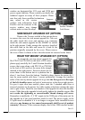
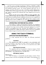
Fit the joint base of PD-2501, PD-2602, PD-305,
PD-306/U, PD-7622 or LM-6201 or the interface bracket
of LM-6301 to the rear connect cover opening. Fit 2
screws with washers to hold the joint tight as in the
picture at right. Then insert the cable into the base mount
device cable groove and cable holder on bottom plate and
connect to the main unit through the base. For low profile
customer display PD-305, the display unit is right on joint base without the
pole.
Remember to enable the +5 V DC supply in the COM port of the
main unit for PD-2501, PD-2602, PD-305, PD-306 or PD-7622 or the +12 V
DC in VGA port for LM-6201 or LM-6301. PD-306U will be powered through
the USB port without specific setting.
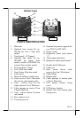
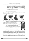
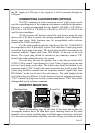
Gen 6 base
Gen 5 base
Gen 5 base