


Part 10
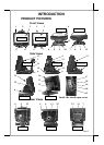
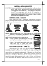
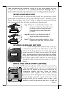
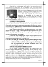
ROUTING THE CABLES
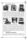
The designed cable routing for all external
cable connections referring to the pictures above is to have all the cables
coming from outside into the cable exit (position A) at bottom side of gen 5
slim base and to be regulated into the two cable holders (B) then enter the base
through the passage (C). The cables should then go through the passage (D) at
top of base box and get out of the base assembly through the opening (E) for
connection to the main unit. Place all the cable ends (F) to be connected to
main unit to come out of the opening (E) from the bottom edge for ease of
later operation. Be sure not to damage any cable during this operation.
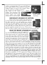
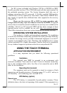
For cable routing in gen 6 super slim base,
please refer to this set of pictures above. To have all external cables pass
through cable ext (A), please release 2 hooks (B) each side over the base trunk
to remove the back cover (C) of base. Inside the base trunk hold all the
external cables with the cable tie (D) and have all cables together with the
HDD cables to pass through an oval hole (E) to come out of the front side of
trunk. Please do not loose off any HDD cable in the operation. Slide each cable
through the twisted passage (F) to enter the rectangular marked rest area for all
the cable ends (G) to be connected to main unit. Be sure not to damage any
cable during this operation.
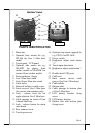
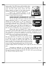
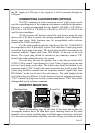
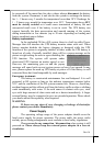
PREPARING THE MAIN UNIT
On the back of the main unit, there is a service window among the 4
matching pegs. Remove the service window lock screw to flip open the cover
plate and find several jumpers as illustrated below. The jumpers in this
B
A
D B
F
C
E
B
A
D
B
G
C
F
E
Gen 6 base
Gen 5 base
Gen 6 base
Gen 5 base
Gen 6 base
Gen 5 base