


Part 7
INSTALLATION GUIDES
CAUTION: Before any installation or cable connection to the set, please
always make certain that the system is turned off and the
external power source to the set is removed to prevent electric
hazard! Never touch any metal pin in the connectors or
circuits to avoid high voltage hazard or electrostatic discharge
damage unless the operator is well grounded. Failure to do the
above will void the product warranty!
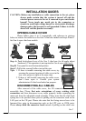
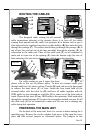
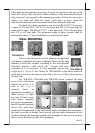
OPENING CABLE COVER
Please follow steps A to C sequentially with reference to pictures
below to remove the cable cover for Gen 5 slim base models and steps B and C
for Gen 6 super slim base models.
Step A: Push lock/release lever of the Gen 5 slim base for tilt angle adjust
backward. (This operation is not required in Gen 6 super slim base)
Step B: Turn panel to most horizontal position
Step C: Pull at the removal hollow toward the user
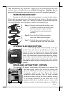
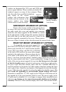
Tips: 1. If there is trouble removing the cable cover, try
pressing the arrowed portion of cable cover in the
rear view picture at right at the same time.
2. If there is still trouble removing the cable cover,
don’t force open it. Consult your system
administrator if it has been locked on purpose.
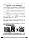
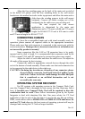
DISCONNECTING ALL CABLES
After removal of the cable cover, the I/O connector area will be
accessible then. Please first note orientations of every existing cable
connection and then disconnect every cable properly before separating the
main unit from the adjustable stand assembly. Please note that the click lock
spring has to be pressed down prior to pulling out the connector such as the
LAN port or the CR port. Please also note that the fixing screws have to be
loosened free prior to disconnection such as the LPT port or COM ports.
Please always hold the connector head instead of pulling on the cable wire
A
B
C
B
C
w/ Gen 5 base w/ Gen 6 base
w/ Gen 5 base
w/ Gen 6 base