Hardware Installation Guide for the Polycom SoundStructure C16, C12, C8, And SR12
2 - 8
have an RJ45 plug form-factor (with a different pinout from standard Ethernet
cables - see Conference Link2 for pinout details) to enable field termination of
custom length cables using standard RJ45 plugs and standard crimping tools.
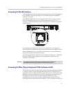
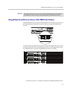
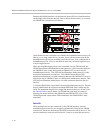
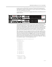
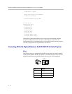
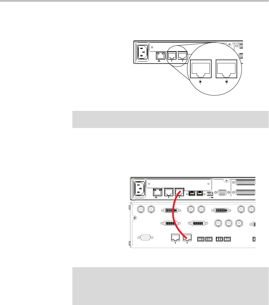
Using the supplied 18” Conference Link2 cable, connect one Conference Link2
port on the SoundStructure device to a Polycom microphone Input port on the
Polycom HDX system as shown in the following figure. If there are multiple
SoundStructure devices linked together with OBAM Link, only one
SoundStructure device should be connected to a Polycom HDX system.
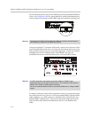
If a longer Conference Link2 cable is required, one may be constructed using
the custom pinout (see Conference Link2) and standard 8P8C (eight positions,
eight conductors, e.g., RJ45) connectors, shielded Cat5e cable or better, and
standard 8P8C crimping tools. Note that the maximum length between the
Polycom HDX codec and the SoundStructure device is one hundred feet
(30m).
90-250 VAC
50/60 Hz
PIN 2: TXD
PIN 3: RXD
PIN 5: GROUND
PIN 7: CTS
PIN 8: RTS
LAN
C-LINK2
OBAM IR
RS-232
R
R
IN OUT
12V
C-LINK2
Warning Connecting a Conference Link2 cable to the Ethernet interface could damage the
connecting device and/or the SoundStructure device.
90-250 VAC
50/60 Hz
PIN 2: TXD
PIN 3: RXD
PIN 5: GROUND
PIN 7: CTS
PIN 8: RTS
LAN
C-LINK2
OBAM IR
RS-232
REMOTE CONTROL 2
REMOTE CONTROL 1
IN OUT
12V
Warning A CAT5e cable that is terminated with standard T568A or T568B pin/pair
assignments will not work with Conference Link2. The Conference Link2 pinout is
different from T568A or T568B pin/pair termination.
Do not use a standard Ethernet cable to connect SoundStructure to a Polycom HDX
system.


