


8
XLR BALANCED INPUTS LEFT & RIGHT: XLR connectors fitted to this amplifier are for use with balanced
line signals from audio preamplifiers. Balanced signals are carried via a three way cable.
The XLR pin configuration used in all Plinius product is:
PIN 1 to GND
PIN 2 to +Signal
PIN 3 to -Signal
NOTE: Because of the way our XLR and balanced inputs are configured it is not possible to connect both
XLR and RCA at the same time.
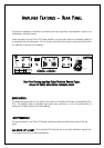
INPUT SELECTION SWITCH
This switch at the centre of the inputs is used to select the pair of input sockets required as described
above. Up selects the RCA input connections, while down selects XLR input.
OUTPUT TERMINALS
Connections for the loudspeakers are provided on the left and right sides of the rear panel. Two parallel
pairs of five way binding posts for each channel are fitted – these provide ease of use with bi-wiring and
multiple cables requiring a large contact area.
GROUND LIFT SWITCH
This switch is located below the remote trigger terminals, and allows the signal ground to be
disconnected from the chassis. In some installations a hum loop may exist due to duplicate ground paths
from different equipment. Use this switch to remove the connection from 0V to ground thus allowing
some flexibility in your particular set-up.
REMOTE TRIGGER TERMINALS
In order to integrate more effectively into a home theatre system, the Plinius P10 has remote trigger
terminals fitted to the rear panel. By connecting a processor with a remote trigger signal to these
terminals, the P10 can be put in and out of standby/mute by the processor to which it is connected.
When in standby/mute the amplifier draws less current and will operate at minimum temperature. The
output relays are also open, disconnecting the loudspeakers. This may be of advantage in a multi-
amplifier and/or remote installations. The standby/mute mode can only be activated via the remote trigger
terminals. Polarity of the connections to the remote trigger is not important.