


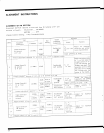

CONNECTION
DIAGRAM
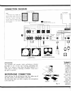
NOTE:
lf connecting
one set
of speaker
sys-
tems
to
speaker
output
terminal
the
speaker
of each
channel
should
be
4
to
| 6 ohms :
however,
both
outPut
terminals
(A, B and C speakers)to
two
speaker
systems the
of
each channel,
8
to 16
ohms.
AM
ANTENNA
AM FERRITE ANTENNA
PRE
OUT
&
MIXING
REC.
pAE
&
t,,tntN
MAIN
IN
JNTfR
COUPLED
PHONO
MAG I
MAG
2
SPEAKER PLUGS
SPEAKER
OUTPUTS
i4
to
| 6()
r
CENTER
CHANNE
OUTPUT
lo)t
Y7
e*cl
TAPE
REC
P.B
/^
TAPE TAPE
MON A
REC. A
I
:'l
-
-4,
I
r
FUSE
5A:
240V
220V
34: |
30V
|
20v
|
10v
#
@
TURNTABLES
(RECORD
PLAYERS)
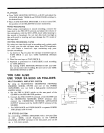
GROUNDING
The
SX-g000
will
provide
stable
performance
whether
grounded
or
not.
In rare case,
however,
grounding
may
help.
If so, connect
a wire
from
the
GND terminal
to
a
water
pipe or balcony,
fastening
it
FIRMLY.
Never use
a
gas
pipe as a
ground.
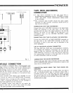
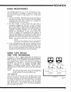
MICROPHONE
CONNECTION
Insert the
plug on the
microphone
cord
into either
one
of
the
MIC
jacks
on the
front
panel
of the
unit.
Use both
jacks
when
you
wish
to employ
two microphones
at the
same time.'
oer!
!
f
...
TAPE DECK
OR
TAPE
RECORDER
MICROPHONE
A
(LEFT
CH.)
TURNTI
.
If the tur
cartridge,
1
termina
crystal
car
Connect
t
right to tl
either
terr
o
A second
used, con.
.
If a tumt
used, eith
separate h
.
Some
tur
terminals
with the s