


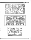

PIONEEFI
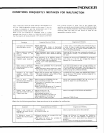
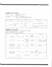
ALIGNMENT
OF MPX
Position
of Switch:
Volume
Control
Settino
Input Signal
:
SECTION
SELECTOR
...
FM AUTO
MUTING
...
OFF
Fully
Counterclockwise
Main
(
L+ R)
40
.5KHz Deviation
(.60,)o
)
l9KHz Pilot
7.5KHz
Deviation
(IO%)
STEPS
Circuit to
be
C onnect
A
I i
gnment
adjusted
Connections
S ignal
R
emarks
+
--
-'-
l
1
2
MPX SG
to
trM
Separation Antenna
terminal
Sub
AC VTVI\4
(L
-R)
XLL
terminal
LorR
LorR
for maximum
deflection
Adjust
for minimum
deflection
of
other
channel.
VRr
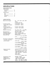
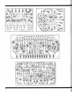
ALIGNMENT
OF AM SECTION
*
VTVM
and oscilloscopeshould
be connected
in
parallel
at
the output.
Position
of Switch:
SELECTOR..................MW
Volume
Control Setting: Fully
Counterclockwrse
I
A dlu st
I
n
emart<s
A Iignment
Adjust
for maximum
sensitivity
and symmet
rical
characteristics.
I nput
TLPS
Lqu,pment
I I
.:',::"
.i,liLt.,
connectrons
l
requency
Point of no
,
Sweep
Generator
]
interference
^
vrVM
t
455kHz
6OdB
i
- - --
Oscilloscope
12
':^:":;;'
8
2
Signal
Generator
60OkHz
600kHz
VTVIM
Antenna
Terminal
30dB
Oscilloscope
^
Tnrougn
dummy
8
3
l
il4ookHz
i
I
14o0kHz
4 Repeat
steps
2 and
3 several
times.
S
T3
T4
T5
A djust
f or maximum
defrection
600kHz
I
60OkHz
Adjust
for
deflection.
maxrmum
Signal Generator
A ntenna
Terminal
through
dummy