


I
TJTONEER
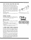
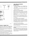
LINE VOLTAGE
SELECTION AND FUSE
SWITCHING
LINE VOLTAGE
SETTING AND
FUSE
To remove
the fuse,
turn the fuse
cap located
on the line
voltage selector
switch
in the
direction indicated
by the
arrow.
Then remove
the fuse
plug
from
the unit. Put
the
fuse
plug
back so
that the
proper
line voltage
marking
can
be seen
through
the cut on
the edge of
the
plug.
Whenever
the position
of the
selector switch
is
changed, check
the
rating
of the
fuse.
A 1.5-ampere
fuse
is
to be used foreither
22OY
or
240V
operation
and
a S-ampere
fuse for 110V,
120V
or
130V
operation.
If
the rating of
the
fuse is
correct,
replace
cap.
FUSE REPLACEMENT
If
the
fuse
blows, remove
the
fuse
cap
and
replace
the
fuse
with a new one.
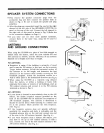
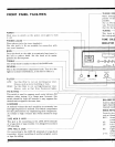
STEREO SYSTEM
The SX-9000
is
general-purpose
stereo
amplifier. Connect it
to the speaker systems
(two
to six),
turntable, tape
recorder,
etc., which are separately
available.
INSTALLATION
When installing
your
stereo
points.
system,
check the following
o
The
place
should
be well-ventilated,
and free from
dampness and dust.
o
The units should
not
be
exposed
to direct sunlight.
o
The units should not
be
placed
near
radiators or other
heating
units.
o
The
place
should
be substantial
and
roomy
enough
for
the
installation, when installing
the unit on a shelf.
A WORD
ABOUT ROOM ACOUSTICS
The
quality
of reproduced
sound
varies
according
to the
size
and shape
of
the
room,
the
materials of
walls, floor
and ceiling
and the amount
and
arrangement of
fumiture.
Too
harsh or
"bright"
a
sound
usually
results from
too
many hard reflecting
surfaces,
and/or
too low
a ceiling.
This condition
is improved
by having ample
carpet
area or
covering
the wall
(especially
that facing
the speakers)
with
a thick curtain.
On the
other hand,
too many
absorbing surfaces
will tend
to
"soak up"
the sound, resulting
in a
certain "deadness".
Furniture may
be rearranged
to
provide
irregular
reflection
of the sound.
In
any event,
the true stereo
effect is lost
if
the two speaker
systems
are
placed
too far
apart. This
may
be corrected
by
angling them
slightly toward
each other
or
reducing
the distance
between
them.
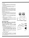
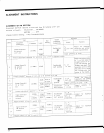
FUSE
CAP
Fig.
1
Take off
the fuse
cap
by turning
it
with
a
coin,
etc. an
the
direction
indicated
by the arrow
mark.
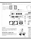
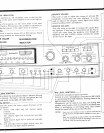
A
SPEAKER
SYSTEM
B SPEAKER
SYSTEM C SPEAKER
SYSTEM
Fig.
2