


Other connections
08
49
En
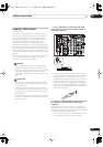
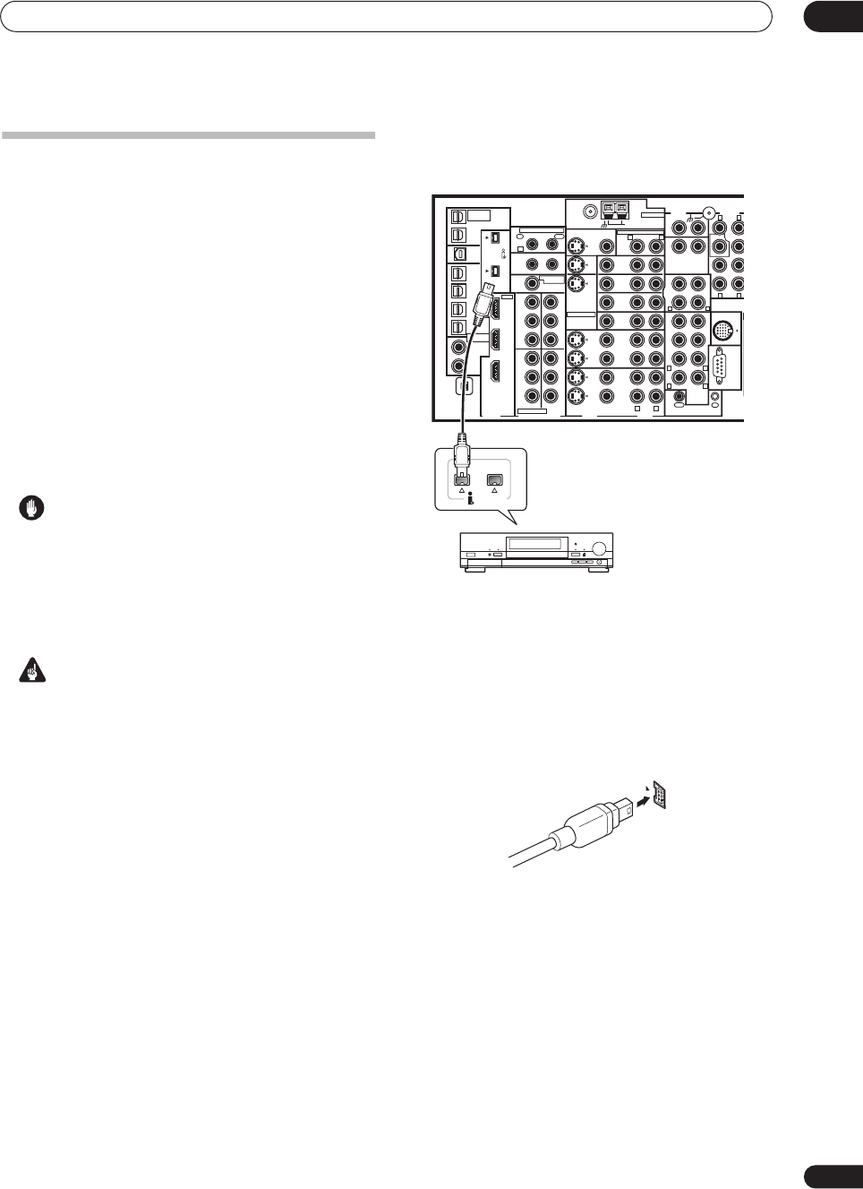
Using the i.LINK interface
VSX-74TXVi only
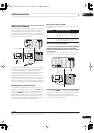
If you have a component with an i.LINK connector, you
can connect it to this receiver using an i.LINK cable.
Since the i.LINK interface does not transmit video
signals, the video signal of i.LINK-connected compo-
nents must be connected with other cables (see
Connecting your equipment
on page 10 for more on
making video connections). If you’ve already hooked up
the video signal from the component, assign the i.LINK
input to the input function to which you’ve connected the
video signals (see
The Input Setup menu
on page 61). See
Checking the i.LINK inputs
below to confirm your i.LINK
settings.
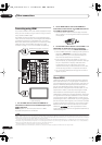
The two i.LINK connectors on the rear of your receiver are
4-pin connectors. Use a 4-pin, S400 i.LINK cable to
connect i.LINK-equipped components.
Caution
• If your i.LINK connector comes into contact with
metallic parts of the receiver other than the i.LINK
terminal, an electrical short may occur. Some cables
have metal parts that may touch the unit when
connected. Please take care to use a suitable i.LINK
cable only.
Important
• Please use 4-pin, S400 cables less than 3.5 meters
long. Although longer ones are available, they may
not work reliably.
• There may be cases where the PQLS/rate control
function and/or the i.LINK audio does not work prop-
erly even when connected to i.LINK Audio-compat-
ible equipment.
• Do not connect/disconnect i.LINK cables or switch
on/off any components connected using i.LINK when
the receiver is on.
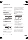
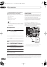
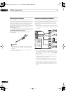
1 Use an i.LINK cable to connect one of the i.LINK
connectors on this receiver to an i.LINK connector on
your i.LINK component.
• The arrow on the cable connector body should be
lined up with the arrow (to the left of the connector)
on the receiver for correct alignment. The i.LINK
cable should be inserted straight into the connector
so that it snaps easily into place. If not connected
properly the receiver will not be able to recognize any
connected components. Note that the i.LINK cable is
fragile and can be broken easily if too much force is
used when connecting.
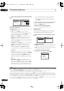
2 Assign the i.LINK component to the input you want,
then make any necessary output settings on the
component.
See
The Input Setup menu
on page 61 to assign the
component to an input function on this receiver. Follow
the operating instructions that came with the component
to make any necessary output settings.
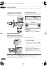
• You can connect several components together using
i.LINK. See
Creating an i.LINK network
below.
S400
(AUDIO)
S400
MULTI-ROOM
&SOURCE
/REC SEL
OUT1
ROOM3(ZONE3)
OUT2
USB
AUDI O
IN
IN
1
(SAT)
IN
2
(DVR/
VCR 1)
IN
3
(DVR/
VCR 2)
IN
4
(CD-R)
1
–
2
1
–
3
1
–
4
IN
1
(DVD/
LD)
IN
2
IN
1
(DVD/LD)
IN
2
(TV)
IN
1
IN
1
IN
2
IN
3
IN
3
OUT
MULTI-ROOM
& SOURCE
MULTI-ROOM & SOURCE
MONITOR
OUT
12 V TRIGGER
ROOM2(ZONE2)
ROOM2(ZONE2)
FM UNBAL 75Ω AM LOOP
MONITOR
OUT
OUT
CD
CD-R/
TAPE
DVD/
LD
TV
SAT
VIDEO1/
GAME1
OUT
DVR/
VCR 1
DVR/
VCR 2
OUT
IN
IN
IN
VIDEO
VIDEO AUDIO
S - VIDEO
IN
IN
IN
FR FL
SUB W. CENTER
MULTI CH
IN
RS-232C
SUR-
ROUND
SURROUND
BACK
CONTROL
iPod
SUB W.
F
C
OUT
PHONO
IN
IN
IN
IN
ROOM2
(ZONE2)
IN
(DC OUT 12V TOTAL 50mA MAX)
12
IN
2
(CD)
IN
IN1
IN2
OUT
Y
P
B
PR
Y
P
B
PR
Y
P
B
PR
Y
P
B
PR
DIGITAL
COMPONENT VIDEO
ASSIGNABLE
XM
ASSIGNA-
BLE
1
–
2
ASSIGNABLE
OUT
IN
OUT
ANTENNA
AUDIO PRE OUT
MULTI-ROOM & SOURCE
IR
HDMI
R L
R
R
L
R L
L
R L
R L
R L
(AUDIO)
S400
i.LINK-equipped component
VSX-74TXVi
VSX_74TXVi.book.fm 49 ページ 2005年6月6日 月曜日 午後7時8分