


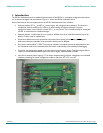
Philips Semiconductors ISP1561 Evaluation Board User’s Guide
UM10005_3 © Koninklijke Philips Electronics N.V. 2003. All rights reserved.
User’s Guide Rev. 2.0—April 2003 8 of 20
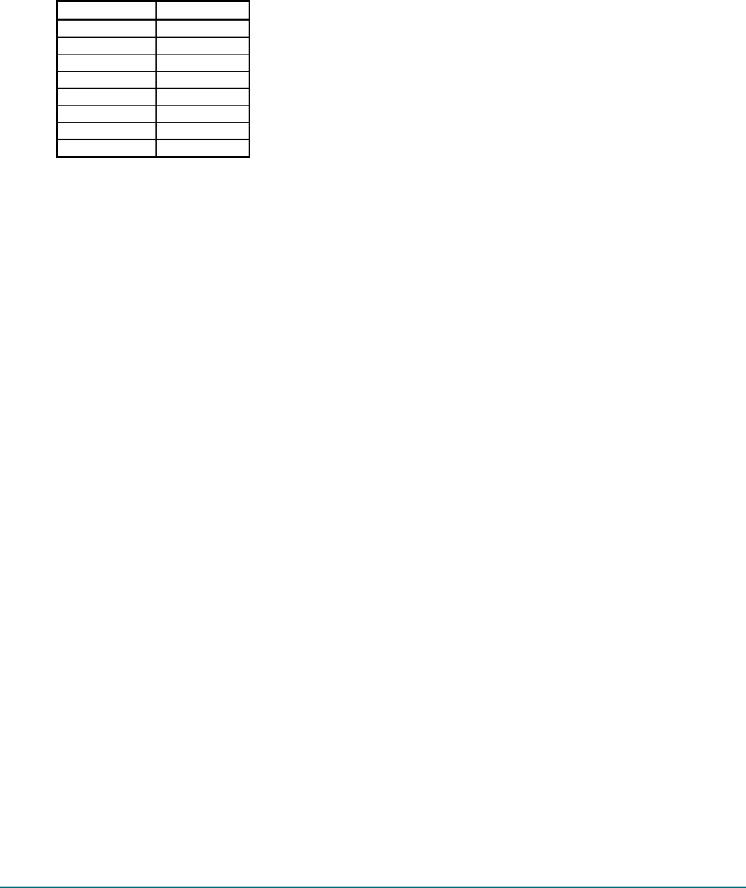
Pin Number Signal
1 GND
2 GND
3 A20OUT
4 SMI#
5 KBIRQ1
6 IRQ12
7 MUIRQ12
8 IRQ1
4.5. Input Clock
You can use either the 12 MHz crystal or the 48 MHz oscillator for the input clock. If the 12 MHz crystal is used,
both the resistors (R1 and R27) are soldered. If the 48 MHz oscillator is used, resistor R27 (0 ) must be
removed and pin 1 is pulled HIGH by R1. By default, the 12 MHz solution is implemented on the evaluation board.
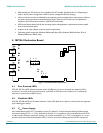
4.6. External 5 V Power Source and S3 Wake-Up Capability
The jack J1 is used for connection of an external +5 V standby power supply to test the system wake-up from
S3cold and maintain the connected USB devices powered so that re-enumeration is avoided.
When the system is in the S3cold Power Management State, the +5 V main power at PCI connectors disappears.
Therefore, all downstream ports will not be powered because V
BUS
is derived from the PCI +5 V power supply. In
this situation, downstream bus-powered devices, such as mouse and keyboard, are not functional and cannot wake
up the system.
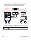
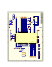
If you want to use the external +5 V supply, pads A and C on the evaluation board must be soldered together as
represented in the evaluation board drawing. Similarly, if you only intend to use PCI +5 V as the V
BUS
power source
(no testing of the system wake-up from S3cold and no external +5 V connected), then pads B and C must be
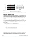
soldered together. Pads A, B and C are copper areas on the upper-right corner of the evaluation board (see Figure
4-1). This solution, using three copper pads, was adopted to avoid using a jumper because only the default
configuration (pads B and C connected together) will be used most of the time.
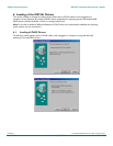
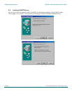
4.7. Loading the Subsystem ID and Vendor ID from the External EEPROM
Expansion board vendors can use the Subsystem Vendor ID and the Subsystem ID for identification of the board
and loading of the correct drivers by the operating system. The PCI SIG assigns the Subsystem Vendor ID and the
vendor determines the Subsystem ID.
The Subsystem Vendor ID and the Subsystem ID can be optionally loaded at power-on from the external serial
I
2
C-bus® EEPROM present on the ISP1561 evaluation board. A 3.3 V serial EEPROM of any size can be used
because only a few locations will be used for data loading.
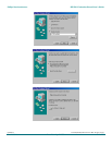
The serial I
2
C-bus EEPROM present on the ISP1561 evaluation board cannot be programmed onboard. It should be
preprogrammed by using a standard serial EEPROM programmer. A socket is provided on the ISP1561 evaluation
board for repetitive reprogramming of the EEPROM.
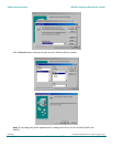
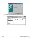
An example on the I
2
C-bus EEPROM programming is given in Figure 4-3. In the example, it is assumed that the
Subsystem Vendor ID is 1132H, the Subsystem Device ID for OHCI is 1664H, and the Subsystem Device ID for
EHCI is 1665H.