


Philips Semiconductors ISP1561 Evaluation Board User’s Guide
UM10005_3 © Koninklijke Philips Electronics N.V. 2003. All rights reserved.
User’s Guide Rev. 2.0—April 2003 6 of 20
• Motherboard with PCI slots that are compatible with PCI Local Bus Specification, Rev. 2.2 (Supporting at
least S1 and S3 power management modes for power management features testing.).
• Memory: Minimum amount as indicated by the operating system and applications requirements, similar to
processor speed requirement mentioned earlier. Only a small amount of memory is occupied by the
installation of the device drivers itself or OHCI/EHCI functionality.
• HDD space: Mainly determined by the operating system and applications requirements because specific
drivers need very little space.
• Graphics cards, other adapter cards: No special requirements.
• Operating systems supported: Windows 98 Second Edition (SE), Windows 2000, Windows XP and
Windows Millennium Edition (Me).
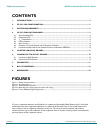
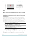
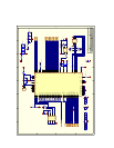
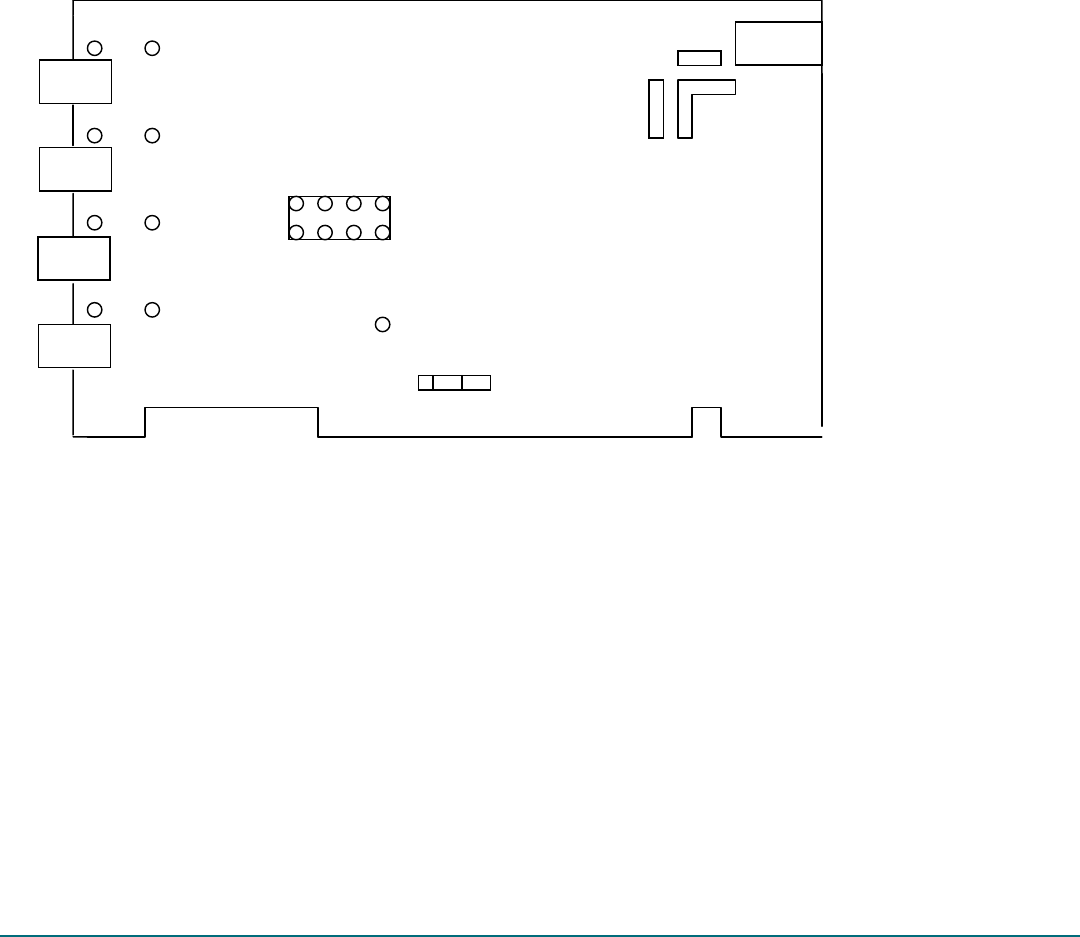
4. ISP1561 Evaluation Board
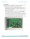
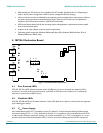
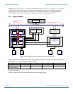
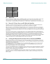
Figure 4-1: Evaluation Board Schematic
4.1. Port Powered LEDs
LEDs D2, D3, D4 and D5 indicate the power status of USB ports. If a port is powered, the respective LED is
turned on. It is turned off during system boot-up until OHCI or EHCI drivers are loaded, or it is switched off
whenever an overcurrent condition occurs.
4.2. GoodLink LEDs
LEDs D6, D7, D8 and D9 are GoodLink indicators. These LEDs blink when a device is connected to the respective
port indicating port activity.
4.3. V
AUX
Power Supply
If the motherboard used is PCI 2.2 compliant, jumper JP1 position 2-3 may be shorted, allowing S3cold suspend
and resume testing (PCI V
AUX
= 3.3 V is used and an external +5 V is necessary). If the motherboard used is PCI 2.1
or older version compliant, jumper JP1 position 1-2 must be shorted (PCI V
CC
= 3.3 V is used because V
AUX
is not
present). Note that in both these situations LED D1 must be turned on indicating that the ISP1561 is powered.
DI
J
P1
3 2 1
D4
D5
D2
D3
D6
D7
D8
D9
1 3 5
7
2 4 6
8
J
P2
J
1
A
BC
PORT1
PORT2
PORT3
PORT4