


Philips Semiconductors ISP1561 Evaluation Board User’s Guide
UM10005_3 © Koninklijke Philips Electronics N.V. 2003. All rights reserved.
User’s Guide Rev. 2.0—April 2003 7 of 20
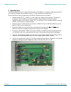
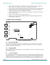
Important: If the LED D1 is not lit, it indicates that the ISP1561 does not have the V
AUX
supply (V
AUX
is not supplied
in the PCI connector). Therefore, your computer will stop responding or ‘hang’ when the operating system is
loading OHCI or EHCI drivers. Switch JP1 to position 1-2 to connect to the PCI V
CC
= 3.3 V (present under
normal conditions, except some system power management modes, for example, S3cold and S4).
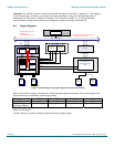
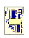
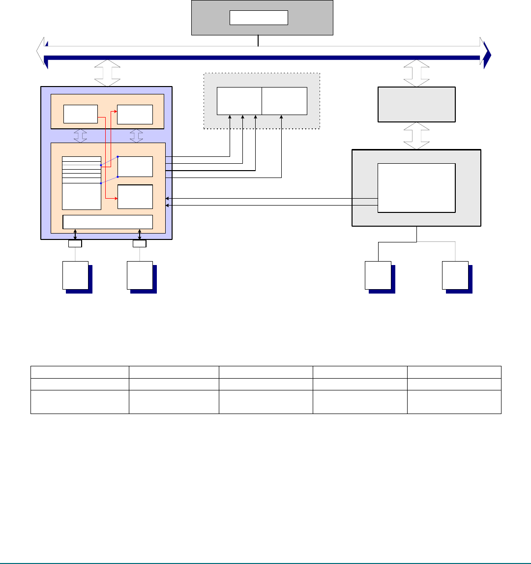
4.4. Legacy Support
Figure 4-2: Block Diagram of Legacy Signal Connection and Testing
Figure 4-2 shows the necessary connections for testing the legacy support functionality. The necessary signals must
be accessible on the motherboard used for legacy testing.
Testing R22 R23 R2 R3
Legacy support —
[1]
—
[1]
10 k 10 k
Default setting
(No legacy support)
0 0 10 k 10 k
[1] When testing the legacy support, resistors R22 and R23 (or the pull-down resistors located at the bottom of the evaluation
board) must be removed.
The JP2 connector is used for testing the keyboard and mouse legacy support.
P C I B U S
PCI Bridge...
Legacy Mouse and
Keyboard Controller
80c42
Legacy Support
Emulation Reg
RootHub
Legacy
Keyboard
Legacy
Mouse
USB
Keyboard
USB
Mouse
System Chipset
KBIRQ1
MUIRQ12
System Memory
Controller
A20OUT
System Interrupt
Controller
IRQ1
IRQ12
SMI#
SMM
System BIOS
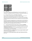
LegacySupport
LegacyEnable
00H
100H
Config Memory
Access
Fixed I/O 60H
and 64H Access
Target Access
10CH
Memory map
IO map (60H and 64H)
System Chipset
OHCI
...
Operational
Registers
104H
108H
Legacy
Emulation
Handler
MemEnb
IOEnb
Fixed I/O 60/64H access is
enabled by the
EmulationEnable (EE) bit
Fixed I/O 60/64H access can be disabled
or subtractive decode is used