


1997 Feb 27 9
Philips Semiconductors Product specification
IF amplifier/demodulator for FM radio receivers TDA1597
Note
1.
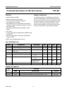
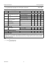
Tuning stop detector
∆f
STOP-0
detuning frequency for STOP-0
(pin 15)
V
15
≥ 3.5 V; see Fig.11 −−26 kHz
V
15
≤ 0.3 V; see Fig.11 38 −−kHz
∆f
STOP-1
detuning frequency for STOP-1
(pin 14)
V
14
≥ 3.5 V; see Fig.10 −−−26 kHz
V
14
≤ 0.3 V; see Fig.10 −38 −−kHz
V
20(rms)
dependence on input voltage for
STOP-0 and STOP-1
(RMS value)
V
14, 15
≥ 3.5 V; see Fig.9 250 −−µV
V
14, 15
≤ 0.3 V; see Fig.9 −−50 µV
R
8
internal low-pass resistance of
detune detector
12 25 50 kΩ
V
8
voltage on capacitor V
i
≤ 5 µV (RMS) on input pin 20;
I
7
=0
− 2.2 − V
Level detector (I
2
=0)
V
6
output voltage V
20
≤ 5 µV (RMS) 0.1 − 1.1 V
V
20
= 1 mV (RMS) 3.0 − 4.2 V
Reference voltage source (pin 5)
V
ref
reference output voltage I
5
= −1 mA 3.3 3.7 4.1 V
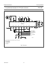
Operation with AM-IF
Level and stop information (on pins 6, 13, 14, 15 and 16) is provided for the modes FM-MUTE-ON and
FM-MUTE-OFF. This information is also available in the FM-OFF mode when an AM-IF signal is input (for example
455 kHz). This can also provide a valid detuning information when a suitable AM-IF resonance circuit is provided for
demodulator (see Fig.18).
SYMBOL PARAMETER CONDITIONS MIN. TYP. MAX. UNIT
α 20
∆V
4FM MUTE– OFF–()
∆V
4FM MUTE– ON–()
-------------------------------------------------------log=