


1997 Feb 27 6
Philips Semiconductors Product specification
IF amplifier/demodulator for FM radio receivers TDA1597
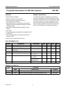
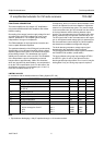
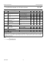
THERMAL CHARACTERISTICS
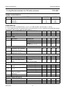
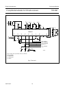
CHARACTERISTICS
V
P
= 8.5 V; T
amb
=25°C; FM-MUTE-ON (I
7
= 0); f
IF
= 10.7 MHz; deviation ±22.5 kHz with f
m
= 400 Hz;
V
i
= 10 mV (RMS) at pin 20; de-emphasis of 50 µs; tuned circuit at pins 10 and 11 aligned for symmetrical stop pulses;
measurements taken in Fig.4; unless otherwise specified.
SYMBOL PARAMETER VALUE UNIT
R
th j-a
thermal resistance from junction to ambient in free air
SOT102-1 80 K/W
SOT163-1 90 K/W
SYMBOL PARAMETER CONDITIONS MIN. TYP. MAX. UNIT
V
P
supply voltage 7.5 8.5 12 V
I
P
supply current I
2
=I
7
=0 − 20 26 mA
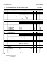
Mode switch input
I
7
input current FM-MUTE-ON − 0 − mA
V
7
input voltage FM-MUTE-ON 2.4 2.8 3.2 V
FM-MUTE-OFF 0.9V
ref
−−V
FM-OFF;
AF attenuation >60 dB
−−1.4 V
IF amplifier and demodulator
Z
i
demodulator input impedance
between pins 10 and 11
25 40 55 kΩ
C
i
demodulator input capacitance
between pins 10 and 11
− 6 − pF
AF output (pin 4)
R
o
output resistance − 400 −Ω
V
4
DC output voltage level V
iIF
≤ 5 µV (RMS) on pin 20 2.75 3.1 3.45 V
PSRR power supply ripple rejection
(pin 4)
f = 1000 Hz;
V
ripple
= 50 mV (RMS)
33 36 − dB
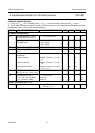
Tuning stop detector
∆f
STOP-0
detuning frequency for STOP-0
(pin 15)
V
15
≥ 3.5 V; see Fig.11 −−26 kHz
V
15
≤ 0.3 V; see Fig.11 38 −−kHz
∆f
STOP-1
detuning frequency for STOP-1
(pin 14)
V
14
≥ 3.5 V; see Fig.10 −−−26 kHz
V
14
≤ 0.3 V; see Fig.10 −38 −−kHz
V
20(rms)
dependence on input voltage for
STOP-0 and STOP-1
(RMS value)
V
14, 15
≥ 3.5 V; see Fig.9 250 −−µV
V
14, 15
≤ 0.3 V; see Fig.9 −−50 µV
V
14, 15
output voltage I
14, 15
=1mA −−0.3 V
Reference voltage source (pin 5)
V
ref
reference output voltage I
5
= −1 mA 3.3 3.7 4.1 V
R
5
output resistance I
5
= −1mA − 40 80 Ω
TC temperature coefficient − 3.3 − mV/VK