


1997 Feb 27 3
Philips Semiconductors Product specification
IF amplifier/demodulator for FM radio receivers TDA1597
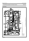
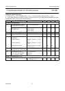
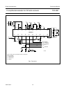
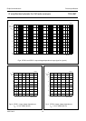
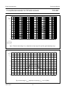
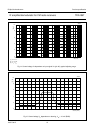
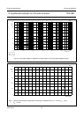
BLOCK DIAGRAM
handbook, full pagewidth
LEVEL
DETECTOR
LIMITING
AMPLIFIER
VOLTAGE
STABILIZER
MODE
SWITCH
QUADRATURE
DEMODULATOR
LP
FILTER
1 MHz
THD
COMPENSATION
unweighted level
information
(FM-MUTE-ON)
adjustment
for minimum
2nd harmonic
(FM-MUTE-OFF)
optional level shift
HP
FILTER
50 kHz
DETUNE
DETECTOR
MUTE
ATTENUATOR
V
int
V
ref
V
ref
V
P
(+8.5 V)
V
offset
V
int
V
int
V
ref
V
int
+5 V
V
ref
V
ref
V
oAF
25
kΩ
25 kΩ
40 kΩ
40
kΩ
3.3
kΩ
7.5
kΩ
25 kΩ
330 Ω
V
int
9 pF
22 nF22 nF
19
(17)
18
(16)
17
(15)
13
(11)
16
(14)
15
(13)
14
(12)
(1)
20
(18)
SFE
FM-IF
input
9 pF
1(1) 2(2) 3(3) 4(4)
(2) (3)
(4)
MPX signal weighted level
information
FM-OFF
+−
MUTE-OFF
5(5) 6(6)
100 nF
7(7) 8(8)
9
47 nF
100
pF
25 kΩ
25 kΩ
STOP-0 STOP-1
n.c.
Q
L
=19
MED829
12
11 (10)
10
(9)
n.c.
×2
TDA1597T
Fig.1 Block diagram and application circuit.
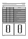
The pin numbers given in parenthesis refer to the TDA1597.
(1) Connecting pin 13 (11) to ground is only allowed to measure the current on pin 16 (14).
(2) FM-MUTE-OFF.
(3) FM-OFF.
(4) FM-MUTE-ON.