Philips Semiconductors Application note
AN1651Using the NE/SA5234 amplifier
1991 Oct
14
10kΩ
10kΩ
10kΩ
12kΩ
40.2kΩ
2.2MΩ
10kΩ
2.2kΩ
220Ω
0.15µF
1µF
4.7µF
1nF
0.47µF
25kΩ
25kΩ
18kΩ
+ –
+
–
+
–
+
–
+
–
A1
A2
A3 A4
100kΩ
4
11
19
8
16
12
11
10
9
74.2V
OFF
ON
0V
X1
D2
D1
C
t
R
A
+4.5V
MIC
R
D
+4.5V
R
3
NE578
NE5234
R
S
SENS.
ADJ.
SL00651
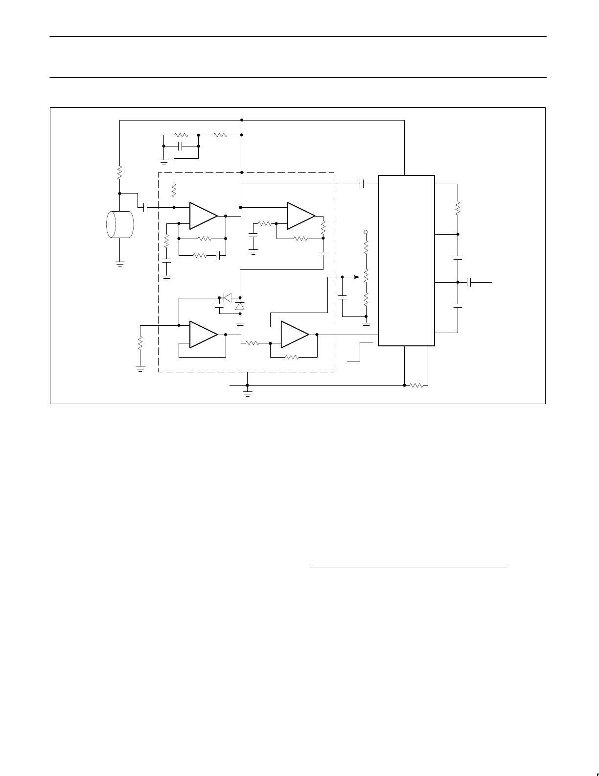
Figure 23. VOX Audio System
Other critical parameters in this type of circuit are the attack and
decay times of the RC network which controls the operation of the
voice operated switch. Attack time determines how quickly the
circuit activates after a quiet period, and the decay time sets how
long the transmitter channel stays active between words. It is
important to reach an optimum balance between the two time
constants in order to allow unbroken transmissions of good quality
and no lost syllables. A 100 to 1 attack/decay ratio is used in this
particular application and this is primarily set by the value of R
A
and
R
D
. A typical delay of two seconds is easily accomplished. Due to
extremely high input impedance of the buffer stage A3, R
D
may be
in the 1 to 2MΩ range allowing a reasonable value of storage
capacitor to be used.
The Audio Channel
Audio input from the preamplifier, A1, is fed directly to Pin 14 of the
NE578 compandor. Referring to Figure 24, which shows the
internal diagram of the device, it can be seen that this is the
compressor portion of the NE578. There is the option in this system
to operate either in a 2:1 compressor mode or an automatic level
control mode, (ALC). The compressor mode simply makes a 2:1
reduction in the amplitude dynamic range of the input signal and
brings it up to the chosen nominal 0dB output level which is
programmable from 10mV
RMS
to 1V
RMS
. In this particular example
it is programmed for a 0dB level of 0.42V
RMS
which is approximately
1V
P-P
. This allows for a standardized output level with good
characteristics for FM modulation where peak deviation must be
controlled. Figure 25 shows the input-output characteristics of the
compressor and ALC.
The compressor also has an attack time determined by capacitor C6
on Pin 11. Attack time is 10k * C6, decay time equals four times this
value. An auxiliary amplifier stage is used following the NE578 in
order to allow bandwidth and special forms of equalization to be
implemented. Note that 2:1 compression in a transmission will
enhance the channel dynamic range and may be used with no
further processing at the receiver, but feeding the received signal
through the complimentary 2:1 expandor will achieve even greater
enhancement of the recovered audio. The NE578 contains both
operations in the same package. Please refer to Philips
Semiconductors applications note AN1762 by Alvin K. Wong for
complete information on these compandor circuits using the NE578.
Fiber Optic Receiver for Low Frequency Data
(Figure 26)
This application makes use of the NE/SA5234 to detect photo-optic
signals from either fiber or air transmitted IR (Infra-red) pulses. The
signal is digitally encoded for the highest signal-to-noise ratio. The
received signal is sensed by an IR photo diode which has its
cathode biased to half the supply voltage (2.5V). The first gain
stage is configured as a transimpedance amplifier to allow
conversion from the microampere diode current signals to a voltage
output of approximately 10mV
0-P
. The second stage provides a
gain-of-ten amplifier to raise this signal level to 1V peak amplitude.
This stage is directly coupled from the preamplifier stage in order to
provide the necessary common-mode voltage of 2.5V. Its gain
control network is capacitively coupled to prevent DC gain as is
required in single supply configurations. Since this is essentially a
pulse gain stage, low frequency gain below the signal repetition rate
is not needed. The third stage acts in a limiting amplifier