


16 Pelco Manual C585M-B (11/98)
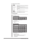
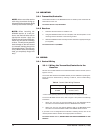
3.3.2 Auxiliary Functions
The Wiretron receiver is capable of operating up to four remotely activated auxiliary
functions. Each auxiliary output may be individually converted at the receiver for
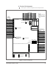
momentary or latching operation. Refer to Figure 8 to set jumpers for auxiliary func-
tions. When in the latching mode, activating the same AUX function will toggle the
function from on to off.
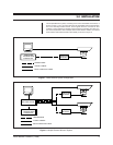
The AUX outputs are buffered to provide a continuous 10 VDC at 25 mA to drive
small relays, lights or other external devices such as gates. Refer to Figures 9 and
10 for examples of typical circuits used for auxiliary functions.
Proceed to Section 3.3.3, VIDEO WIRING.
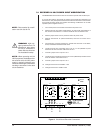
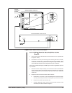
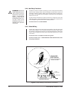
3.3.3 Video Wiring
Install a video cable from the video output of the camera to the video input of the
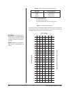
monitor (refer to Figures 1 and 2.) Proper termination of the video cable is vital to
the operation of the equipment. Be sure 75-ohm cable termination is made at the
monitor. Refer to Table B when wiring video coaxial cable distances up to 1,500 ft
(457 meters).
Proceed to Section 3.4, POWER, if finished wiring video.
Proceed to Section 3.3.3.1, LONG DISTANCE CABLE INSTALLATION, when
wiring longer distances.
WARNING:
Mechanical
relays used must not ex-
ceed 10 VDC at 25 mA.
Applications with higher
power requirements
should be used with the
AUX2000 Auxiliary Con-
trol Box. Refer to the
AUX2000 manual for in-
stallation and operation
instructions.
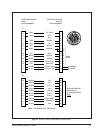
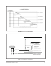
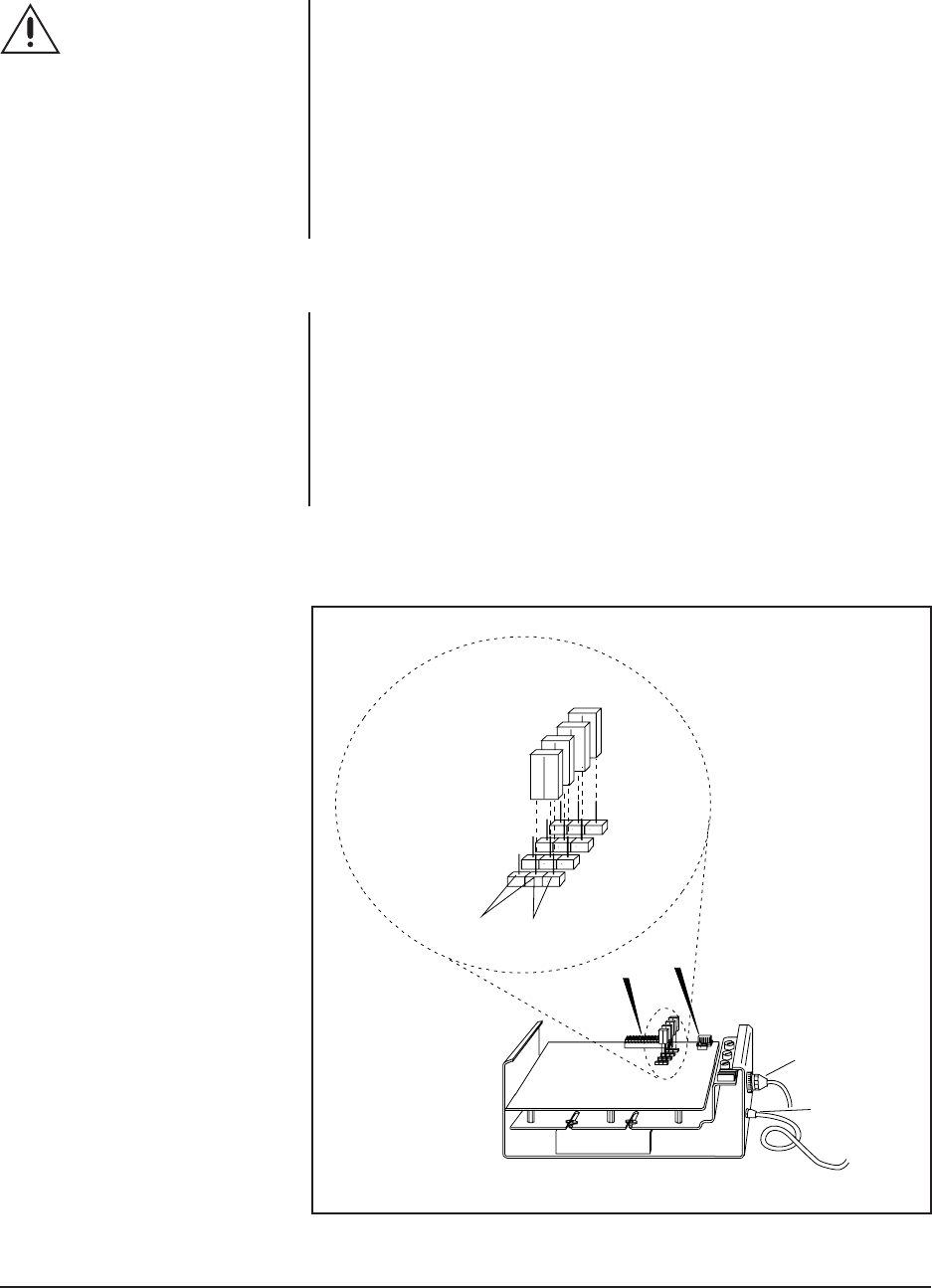
Figure 8. Jumper Settings on the Receiver Circuit Board
AUXILIARY JUMPER
SETTINGS ON THE
WIRETRON RECEIVER
BOARD. JUMPERS ARE
SHOWN IN THE MOMENTARY
“POSITION” OR “MODE”.
WIRETRON RECEIVER
LATCHING
MOMENTARY
JP1 AUX1
JP2 AUX2
JP3 AUX3
JP4 AUX4
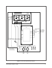
P 1
P 2
37-PIN
CONNECTOR
POWER INPUT
CIRCUIT BOARD