Pelco Manual C585M-B (11/98) 13
3.3.1.2 Wiring from the Receiver/Driver to the
Pan/Tilt
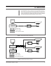
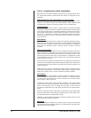
1. Run multi-conductor cable between the receiver/driver and the pan/tilt (refer
to Figures 1 and 2.)
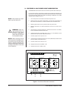
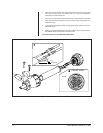
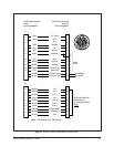
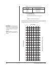
2. Assemble the connector parts according to the following instructions. Detail B,
in Figure 6, reflects the pin arrangement specific to the WX8000 Series
receiver/drivers. Refer to Figures 6 and 7 during assembly. For best results,
use an AMP style crimper when making the wire-to-pin connection.
The instructions that follow apply to all AMP style connectors regardless of pin size
or pin number.
1. Slide the connector clamp assembly over the conductor cable. If the diameter
of the conductor cable is such that the rubber boot will slide over it easily then
slide the rubber boot onto the conductor cable at this time. If not, discard the
rubber boot.
2. Prepare the wires from the conductor cable as follows:
a. Strip at least 1-inch (2.54 cm) from the cable jacket to expose the wires.
You may need to strip more from the cable jacket if you have more wires.
b. Strip 1/8-inch (0.318 cm) from each wire.
c. Using an AMP style crimper, crimp the wires and their insulation to the
connector pins. Refer to Detail A in Figure 6.
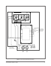
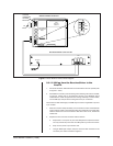
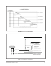
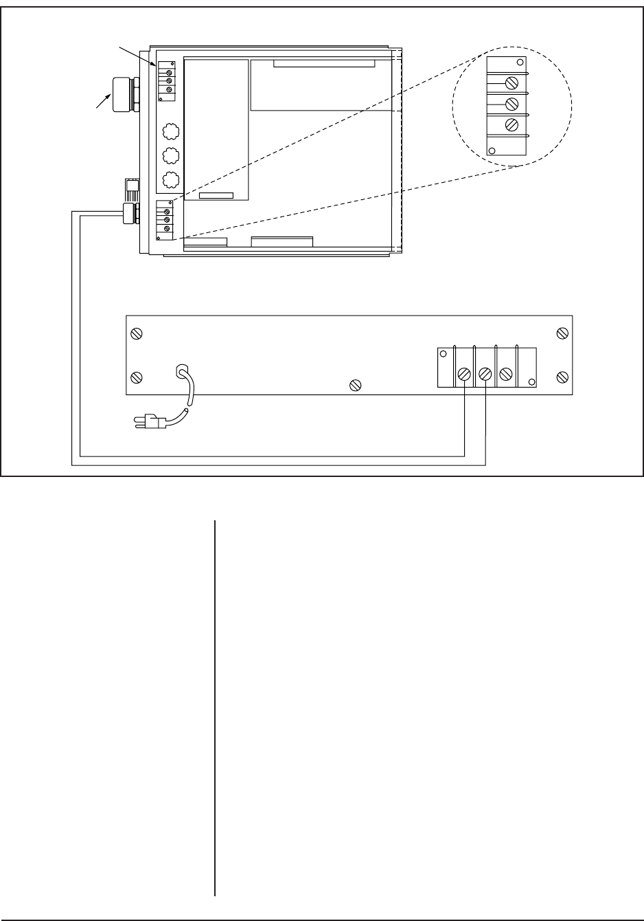
Figure 5. Basic Wiretron Interconnect Diagram
AC INPUT
TB1
HI LOW GND
HI
LOW
GND
AUTO/RANDOM
SCAN MODULE
A9000
TEST
MODULE
CX900TLC
HI LOW GND
F3
F2
F1
PS 1 8
10 1 P2
P1 1 14
J2
3
2
1
AC
LOW
GND
AC
HIGH
22 1 P3
CAUTION:
HAZARDOUS
VOLTAGE
MAY EXIST
AC
INPUT
WX8000 SERIES RECEIVER
MPT8000 SERIES CONTROLLER


