10 Pelco Manual C585M-B (11/98)
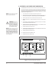
3.1 RECEIVER 24 VAC POWER INPUT MODIFICATION
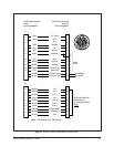
The WX8024RX series receivers can be converted to operate with 24 VAC input.
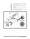
To convert the receiver, disconnect the receiver circuit board and assembly from
the enclosure. The patch panel circuit board is located on the bottom of the receiver
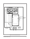
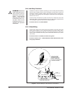
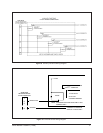
circuit board mounting plate and requires the following modifications for 24 VAC
operation (refer to Figures 3 and 4.)
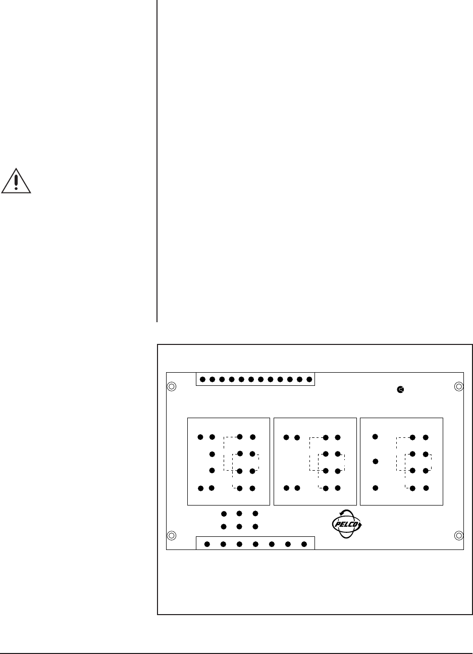
1. Turn off the power to the receiver and remove the power cord.
2. Remove all wires from patch panel sections T2 and T3 with the exception of
the red wire connected to T3-1 and the red/white wire connected to T3-3.
3. Remove jumper wires from J4 pins 8 and 9 and J5 pins 8 and 9.
4. Remove transformer T2 (small transformer) and store for future use or
discard.
5. On transformer T3 (large transformer), insulate the wire ends on the black,
brown, black/white and brown/white wires.
6. Locate the blue wire connecting fuse F3 to pin 7 of P7 (labeled F3) and
disconnect at the P7 location. Reconnect to T3-3.
7. Connect a jumper from J4 pin 9 to T3-1.
8. Locate the wire connecting fuse F2 to pin 6 of P7 (labeled F2) and disconnect
at the P7 location. Reconnect to T2-3.
9. Connect a jumper from J5 pin 9 to T2-1.
10. Change fuse F2 from 2/10 ASB to 1 AG.
11. Change fuse F3 from 1 ASB to 3 AG.
NOTE:
Parts needed for modifi-
cation: one 3 A fuse for F3.
WARNING:
High volt-
age is present on the T3
transformer wires when
the unit is connected to
power. Be sure the wires
are insulated for safety.
NOTE:
When operating with 24
VAC input power, the distance from
the receiver to the 24 VAC power
supply is typically limited to any
conductor size/length combination
resulting in less than 5 ohms total
circuit resistance.
Figure 3. Circuit Board Electrical Connections
1P6
1P7
PCB1500526
REV. G
MADE IN U.S.A.
T3 T2 T1
24V P/T
24V CAM
28VCT
®
J6
GND
J4
J5 F1 F2 F3
GND
AC LOW
AC HIGH
8
999
88
}
}
J6J4 J5
66 94V0
9648
J2
J1
J3
1
2
3
4
5
6
7
110V
110V
220V
J2
J1
J3
1
3
4
5
6
7
110V
110V
220V
J2
J1
J3
1
2
3
4
5
6
7
110V
110V
220V


