


4
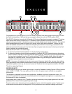
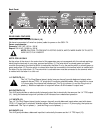
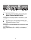
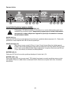
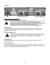
FRONT PANEL FEATURES
EQUALIZER SECTION (1)
There are two 15-band 2/3-octave filter sets. The filters are constant “Q” devices located at ISO center
frequencies. Effective equalization range is from 25 Hz to 16 kHz per channel. Maximum cut per frequency
is 18 dB and the boost per frequency is 12 dB.
AUTOMATIC FEEDBACK LOCATING LEDS (2)
When feedback occurs, the LED of the frequency band that is feeding back will illuminate, indicating the
slider to be adjusted. The LED will remain illuminated for a few seconds even after the feedback is gone.
This is to allow you to see where the feedback is if the feedback goes away before any correction is made. If
there is no feedback occurring, the LED of the frequency band with the most signal in it will illuminate. Just
because the LED is illuminated does not mean that there is feedback occurring.
OPERATING THE FEEDBACK LOCATING SYSTEM
The feedback locating system is normally used in one of two ways.
1. To catch and reduce/eliminate feedback “on-the-fly” during a performance.
2. To determine frequency bands that are susceptible to feedback before the performance, and elimi-
nate them in advance. This is done after the system is set up, by bringing up the microphone levels
slowly to the point of feedback. As they start to feedback, note the LED activity on the Q
™
215FX.
Move the faders to decrease the “identified” bands. Now you have eliminated a high percentage of
potential feedback problems before the performance even begins.
Note: It is not uncommon for feedback to occur over several frequency bands. Also, go easy when making
fader adjustments since extreme movements will affect your performance and be counter productive. Some
feedback or ringing, although audible, may not be louder than the other program material and may not light
an LED.
GAIN (3)
Calibrated control for regulating overall gain of the equalizer section. Unity gain throughout the signal chain
may be maintained by recovering lost signal at this point.
For example: Assume the equalization process has introduced a signal loss of -6 dB by negative (-) adjust-
ment of the EQ section. The gain should then be adjusted to +6 to maintain unity gain through the equalizer.
LOW CUT (4)
Provides high pass filtering at 40 Hz in the “in” position. Low frequency roll-off is at 12 dB per octave.
LOW CUT LED (5)
With the Low Cut switch in the “in” position, this LED will illuminate indicating a low frequency roll-off at
12 dB per octave at 40 Hz
BYPASS LED (6)
This LED will illuminate when the Bypass switch is in the “in” position, indicating that the EQ and gain
controls are bypassed.
BYPASS (7)
In bypass mode (switch in), the input signal is routed directly to the output and is unaffected by all front panel
controls except the low cut filter.
LED LEVEL METER (8)
This multicolored LED ladder indicates output level.
POWER SWITCH (9)
Used to turn AC mains power on or off.