


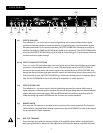
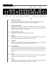
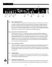

(27) CABINET IMPEDANCE SWITCH
This three-position switch allows appropriate selection of speaker cabinet impedance. If two
enclosures of equal impedance are used, the switch should be set to half the individual value. For
example, two 16 Ohm enclosures necessitate an 8 Ohm setting, while two 8 Ohm enclosures would
require a 4 Ohm setting. Minimum speaker impedance is 4 Ohms.
(28) SPEAKER OUTPUTS
These paralleled 1/4" mono (TS) jacks are provided for the connection of speaker enclosure(s). Again,
minimum speaker impedance is 4 Ohms. The CABINET IMPEDANCE SWITCH (27) should be set to
match the load of the speaker cabinet(s).
(29) LINE OUT LEVEL
This control sets the level of signal being sent out of the LINE OUT (30) jack. It may be used to balance
the level of slave power amp/speaker systems driven from the LINE OUT (30) to the level of cabinets
driven from the SPEAKER OUTPUTS (28).
(30) LINE OUT
This 1/4" mono (TS) jack provides a post-power amp signal to drive another power amp/speaker
system while maintaining the amplifier’s tone.
(31) FUSE
A fuse is located within the cap of the fuse holder. This fuse must be replaced with one of the same
type and value to avoid damaging the amplifier and voiding the warranty. If the amp repeatedly blows
the fuse, it should be taken to a qualified service center for repair.
WARNING: THE FUSE SHOULD ONLY BE REPLACED AFTER THE POWER CORD HAS BEEN
DISCONNECTED.
(32) GROUND POLARITY SWITCH
This three-position, rocker-type switch should normally be placed in the center (0) position. If hum
or noise is noticed coming from the speaker enclosure(s), the switch may be placed in the “+” or “-”
position to minimize hum/noise. If changing the polarity does not alleviate the problem, consult your
authorized Peavey dealer, the Peavey factory or a qualified service technician.
(33) IEC MAINS CONNECTOR
This is a standard IEC power connector. An AC mains cord having the appropriate AC plug and ratings
for the intended operating voltage is included in the carton. The mains cord should be connected to
the amplifier before connecting to a suitable AC outlet.
U.S DOMESTIC AC MAINS CORD
The mains cord supplied with the unit is a heavy duty, three-conductor type with a conventional 120
VAC plug with ground pin. If the outlet used does not have a ground pin, a suitable grounding adapter
should be used and the third wire should be properly grounded.
Never break off the ground pin on any equipment. It is provided for your safety.
NOTE FOR UK ONLY:
If the colors of the wires in the mains lead of this unit do not correspond with the colored markings identifying
the terminals in your plug, proceed as follows: (1) The wire that is colored green and yellow must be connected
to the terminal that is marked by the letter E, the earth symbol or colored green or green and yellow; (2) The
wire that is colored blue must be connected to the terminal that is marked with the letter N or the color black;
(3) The wire that is colored brown must be connected to the terminal that is marked with the letter L or the
color red.
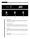
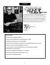
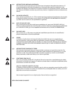
F O OT S W I T CH
(34) CABLE CONNECTOR
This seven-pin DIN connector is provided for connecting the footswitch to the amplifier REMOTE
SWITCH (25) via the cable included in the carton. Connections at the switch and the amplifier should
be made before the amp is powered up.
(35) ULTRA/CRUNCH SELECTOR
This switch selects between the Ultra and Crunch channels on the amplifier. The adjacent LED will
illuminate when the Ultra channel is selected. When the LED is dark, the Crunch channel is selected.
The CLEAN SELECTOR (36) must be in the BYPASS mode to activate either the Ultra or Crunch channel.
(36) CLEAN SELECTOR
This switch selects the Clean channel and will activate regardless of the position of the ULTRA/CRUNCH
SELECTOR (35). The adjacent LED will illuminate when the Clean channel is selected. This switch must
be in the BYPASS position, indicated by a dark LED, in order to utilize the ULTRA/CRUNCH SELECTOR
(35).
(37) EFFECTS SELECTOR
This switch activates the amplifier’s effects loop (21 – 24). The adjacent LED will illuminate when the
effects loop is active.
35
37
34
36
8