


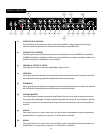
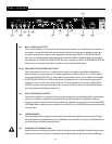

R E A R PA N E L
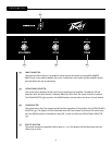
(9) BASS
This control, on both the Ultra and Crunch channels, varies the low frequency response of the
amplifier. It is an active control (shelving type) and allows
˜
12 dB of boost or cut.
(10) VOLUME
This control, on all three channels, sets the overall level of its respective channel.
(11) GAIN
This control, on both the Ultra and Crunch channels, controls the input volume level of the channel.
Rotating this control clockwise will increase the amount of preamp distortion and sustain.
(12) CHANNEL ACTIVATION LEDs
These indicators signify which channel is active. Ultra channel activation illuminates the red LED;
Crunch channel activation illuminates the yellow LED; and Clean channel activation illuminates the
green LED.
(13) FAT SWITCH
These two-position toggle switches on the Ultra and Crunch channels modify the low frequency
responce of the amplifier and have the most noticeable effect when the guitar is "cleaned up," i.e.
with the guitar's volume control turned down. This control affects the tightness of the attack of the
notes; the attack is sloppier when the switch is in the "FAT" position.
(14) NOISE GATE
This control is shared by the Ultra and Crunch channels and adjusts the effectiveness of the noise
gate circuitry. Noise is reduced more as the control is turned clockwise. Avoid using high settings of
the noise gate when using lower gain settings, since at these settings the decay of the note will be
adversely affected.
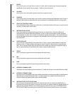
(15) TREBLE
This passive control regulates the high frequencies for the Clean channel.
(16) MID
This passive control regulates the mid frequencies for the Clean channel.
(17) BASS
This passive control regulates the low frequencies for the Clean channel.
(18) HIGH GAIN INPUT
Used for most electronic guitars. It is 6 dB louder than the Low Gain input.
(19) LOW GAIN INPUT
Provided for instruments that have etremely high outputs that tend to overdrive (distort) the High Gain
input. If both inputs are used simultaneously, the output levels are the same (both are Low Gain).
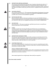
(20) CHANNEL SELECT SWITCH
This three-position toggle switch allows selection between the amplifier’s three channels. LED (12)
illumination indicates which channel is active. Channel switching can also be accomplished by
footswitch. See the FOOTSWITCH section of this manual for explanation of switch operation. The
CHANNEL SELECT SWITCH must be set in the Ultra position in order for the footswitch to operate
properly.
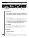
(21) EFFECTS SEND LEVEL
This calibrated (0 – 10) control sets the level of signal being sent to external effects and/or signal
processors. Clockwise rotation increases the amount of signal being sent; counterclockwise rotation
decreases the amount. For the quietest operation, the EFFECTS SEND LEVEL should be set as high as
possible. Generally, the SEND and RETURN levels should be set oppositely. If the EFFECTS SEND LEVEL
is set low, the EFFECTS RETURN LEVEL (24) is set high to achieve unity gain. If volume boost is desired,
turn both controls to higher settings.
(22/23) EFFECTS SEND/EFFECTS RETURN
These 1/4" mono (TS) jacks allow signal to be sent to and returned from external effects and/or signal
processors. Using shielded cables with 1/4" mono (TS) phone plugs, patch from EFFECTS SEND to
the input of the external device and from the output of the external device to EFFECTS RETURN. Only
devices that do not increase signal gain should be used in this effects loop (chorus, delay, reverb, etc.).
If the footswitch is used, the EFFECTS SELECTOR (37) switch must be depressed to activate the effects
loop. See the FOOTSWITCH section of this manual for explanation of switch operation.
(24) EFFECTS RETURN LEVEL
This calibrated (0 – 10) control sets the level of signal being returned from external effects and/or
signal processors. Clockwise rotation increases the amount of signal being returned; counterclockwise
rotation decreases the amount. Again, SEND and RETURN levels should be set oppositely, with the
SEND level being high and the RETURN level low to ensure the quietest operation.
(25) REMOTE SWITCH
This seven-pin DIN connector is provided for the connection of the remote footswitch. The footswitch
cable should be connected before the amp is powered up. See the FOOTSWITCH section of this manual
for an explanation of switch operation.
(26) BIAS TEST TERMINALS
These terminals are provided to measure the bias of the amplifier’s power tubes. A knob behind the
back panel grill allows for adjustment. Bias adjustment should only be done by a qualified technician.
22
24 26
21
25
27
2923
28 30
32
31
33
6