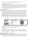
SPEAKER OUTPUTS (18) (19)
Two l/4” jacks and 5-way binding post speaker output terminals are provided for each channel, with all the
outputs from each channel in parallel. Thus, the loudspeaker connection cables can be terminated with
l/4”
phone plugs, banana plugs, or stripped wires for use in the binding post terminals. For sustained high-power
applications, the use of the binding post terminals is highly recommended; however, care must be exercised
to assure correct speaker phasing. Regardless of what connections are used, the typical parallel speaker load
should always be limited to 2 ohms per channel or 4 ohms BRIDGE mode for any application. Operation at
loads of 4 ohms per channel or 8 ohms BRIDGE mode is more desirable for sustained operation applica-
tions, because the amplifier will run much cooler at this load. Operation above 4 ohms per channel and
even open-circuit conditions can always be considered safe; however, sustained operation at loads below 2
ohms could result in temporary amp shutdown due to operation of the thermal limiting and/or the fault
detection circuitry.
INSTALLATION AND CONNECTION
The Peavey CS 1000X Commercial Series Power Amplifier is designed for durability in commercial instal-
lations and quality of performance required in studio and home applications. The unit is a standard
19”
rack-mount configuration that requires 5 l/4” rack height; it is cooled by an automatic two-speed internal
fan. The front panel contains various LED indicators for the monitoring of power output, DDT activation,
and thermal shutdown. Detented and calibrated input sensitivity controls and a heavy-duty mains power
switch are also provided. All inputs, outputs, and patch points are on the back panel.
MAINS POWER SOURCE
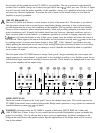
If possible, each amplifier should be connected to separate mains circuits capable of delivering at least 15
amps continuously. This is most critical for sustained high-power applications into 2 ohms per channel. For
lesser loadings, it is possible to use two amplifiers per mains circuit, each having a 20-amp capability. Never
break off the ground pin on the CS 1000X. Always use a qualified electrician to install any necessary elec-
trical equipment. To prevent the risk of shock or fire hazard, always check to see that the amplifiers are
properly grounded.
INDUSTRIAL AND COMMERCIAL INSTALLATIONS
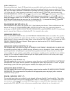
For commercial and other installations where sustained high-power operation is required, the amplifiers
should be mounted in a standard 19” rack. It is not necessary to leave a rack space between each amplifier in
the stack, since the fan pulls air in from the rear and exhausts the hot air out of the front. An adequate cool
air supply must be provided for the amplifiers when rack-mounted. The internal fan must have a source of
air that is not preheated by other equipment. The amplifier will start up in low-speed fan operation and will
normally stay at low-speed operation unless sustained high-power operating levels occur. As the amplifier
heat sinks heat up, the automatic thermal-sensing circuitry will cause high-speed operation to occur. De-
pending upon signal conditions and amplifier loading, high-speed fan operation may continue, or the fan
may cycle continuously between high and low. This situation is quite normal. If cooling is inadequate due to
preheated air, or a reduction of air flow occurs due to blockage of the inlet or outlet ports, or if the amplifier
is severely overloaded or short-circuited, the internal thermal-sensing system may cause temporary shut-
down of that particular channel. Depending upon the availability of cool air, operation should be restored in
that channel relatively quickly. In any case, corrective action should be taken to determine the cause of the
thermal shutdown. If the amplifier is not severely overloaded or short-circuited, and air flow is normal in the
amplifier, steps should be taken to provide a cooler environment for all the amplifiers. As a general rule, the
cooler electronic equipment is operated, the longer its useful service life will be.


