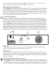
The term headroom deserves some consideration. Program material (music or speech) is made up of many
different frequencies and their harmonics. Most music, especially contemporary rock music, is bass-heavy.
That is, the low-frequency material contains much more energy than the high-frequency material. If both
high- and low-frequency material, such as voice and bass guitar, are present in a full-range system, the
high-
energy bass frequencies can use up most of the power available from the power amplifier, leaving little (or
none) for the high frequencies. The result usually is severe clipping (distortion) of the high-frequency
material. In a biamplified system, the high-frequency material is routed to its own power amplifier (and
associated loudspeaker), which avoids the clipping problem. This results in an effective increase in system
headroom that is greater than that which is obtained by simply using a second power amplifier/speaker
combination in full-range operation. To biamp, then, some type of active crossover is employed in the mixer
feed to separate the low- and high-frequency material, which is then patched to separate power amplifiers to
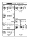
drive separate loudspeaker components. Such a system is easily accomplished with the Peavey CS 1000X
power amplifier patch panel and associated CS Series plug-in active crossover modules.
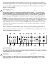
The Peavey DDT compression system adds a totally new dimension to the typical biamped system. Each
power amplifier channel now has its own Distortion Detection Technique circuitry, and each is completely
independent. When signal conditions exist that could cause clipping in the low-frequency power amp
channel(s), the DDT system will simply limit that portion of the total biamp system. This will in no way
affect the high-frequency portion of the biamp system, and it is free to increase in level until conditions exist
that could cause clipping in that particular power amp channel(s). At that point, the DDT system will limit
the high-frequency portion of the system. This is a very effective two-level compression system and will
yield sound pressure levels unmatched by conventional broad-band compression techniques.
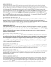
BIAMP SYSTEM NOTES
1.
A biamp configuration is only possible with loudspeaker systems that provide access to the
individual speaker components, bypassing the built-in passive crossover (most Peavey systems offer
biamp high and low switching jacks on the back panel).
2.
The crossover module used must have the proper characteristics to match the particular loudspeaker
system. Of greatest importance is the crossover frequency. Peavey offers a variety of plug-in
crossover modules that are specifically designed to match the various loudspeakers in the Peavey
product line. These crossovers have the correct crossover frequency, high-frequency pad, and
equalization for the particular loudspeaker, resulting in system performance with a very flat
frequency response. Also available are general purpose crossover modules at various frequencies
from 100 to 5000 Hz for non-Peavey loudspeaker systems.
3.
The outputs of the crossover modules (both high and low) can drive several power amp inputs. The
parallel input jacks can be used to daisy-chain to additional power amps for an expanded system on
either the low- or high-frequency system (or both). Remember, the components in most Peavey
biampable speaker systems are 8 ohms. All Peavey CSX series power amplifiers are now rated at
2 ohms. This means that the allowable maximum number of components connected to any one
particular power amplifier channel is four (four horns, four woofers). If additional components are
required in larger systems, more power amp channels are needed. Often experienced sound
technicians limit the maximum number of components to three per power amp channel. This practice
allows the power amplifiers to run much cooler and creates a system that is less likely to shut down
thermally in a high-temperature environment!
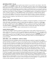
4.
The PL-2 transformer module can be removed and the jumper reinstalled in any particular crossover
island if a balanced input is not desired or required for the crossover module. In this case, the
associated XLR connector (11) is now unbalanced as per previous discussion. If desired, the parallel
unbalanced phone jack inputs (13) may be used to supply signal to the crossover module. In
addition, whenever the XLR connector on a particular crossover island is used (either balanced or
15


