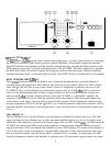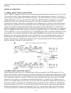
LOW-Z INPUTS (11)
Conventional three-pin, female XLR input jacks are provided, which can be used as either the channel
inputs or the crossover inputs, depending upon what has been plugged into the crossover socket (14). Fur-
ther, this XLR input is balanced or unbalanced, depending upon what is plugged into the transformer socket
(12). When the (PL-2) line-balancing transformer is used in socket
(12),
this XLR input becomes fully
TRANSFORMER-BALANCED, with pin
#3
as the positive input and pin
#2
as the negative input. When a
blank plug (PL-1) is inserted in socket
(12),
this XLR input becomes unbalanced, with pin
#3
as positive
input and pin
#2
as ground. If a PL-MODULE ELECTRONIC CROSSOVER is plugged into socket
(14),
the XLR input system drives the crossover, but if a blank plug (PL- 1) is inserted in socket
(15),
the XLR
input system is connected directly to the channel power amp input.
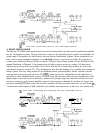
TRANSFORMER RECEPTACLES (12)
These receptacles only receive the optional (PL-2) line-balancing transformer. When conditions exist that
demand the usage of a TRANSFORMER-BALANCED XLR at the input of a power amp channel or
at the input of the PL-MODULE ELECTRONIC CROSSOVER when BIAMPING, the (PL-2) transformer
must be inserted here. Otherwise a blank plug (PL-1) is inserted in this socket.
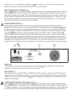
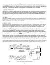
CROSSOVER INPUTS (13)
These are the HIGH-Z INPUTS when an ELECTRONIC CROSSOVER module is installed. Two parallel
input jacks are provided at this point, allowing flexible Y-cord capability. The output of the LOW-Z XLR
input circuitry is always connected to these inputs, which allow the LOW-Z INPUT to be used as the ELEC-
TRONIC CROSSOVER input if desired. These inputs can then be used as FULL-RANGE outputs for
additional patching capability.
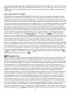
CROSSOVER MODULE RECEPTACLE (14)
This receptacle may only receive a plug-in PL-MODULE ELECTRONIC CROSSOVER. PL-MODULES
are optional accessories and are available in many different crossover frequencies. Some modules contain
special equalization and padding for a particular Peavey speaker enclosure. Always be sure to select the
correct module for your speaker system. Other special-purpose modules are also available for use with this
receptacle. This receptacle supplies both the input and output patch facilities as well as the power supply
“feeds” for these active electronic devices.
CROSSOVER LOW OUTPUT (15)
This jack supplies the crossed-over low-frequency output from the installed PL-MODULE ELECTRONIC
CROSSOVER. This output must be patched to the appropriate power amp input jack to “create” an opera-
tional biamp system. On some special-purpose modules, this output jack is not used.
CROSSOVER HIGH OUTPUT (16)
This jack supplies the crossed-over high-frequency output from the installed PL-MODULE ELECTRONIC
CROSSOVER. This output must also be patched to the appropriate power amp input jack to create an
operational biamp system.
POWER AMPLIFIER INPUT (17)
Two parallel input jacks are provided for each channel, delivering flexible Y-cord capability. These jacks
can be considered the normal power amplifier high-Z input. If a blank plug (PL-1) is inserted in the cross-
over accessory socket
(14),
the associated XLR input system is connected to these input jacks internally,
permitting the XLR input (11) to be a direct power amplifier input without the use of a patch cord.
7


