


Connections
WARNING
! Use speakers over 50 W (output value) and
between 4 W to 8 W (impedance value).Do
not use 1 W to 3 W speakers forthis unit.
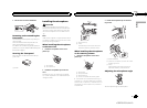
! The black cable is ground. When installing
this unit or power amp (sold separately),
make sure to connect the ground wirefirst.
Ensure that the ground wire is properly con-
nected to metal parts of the car’s body. The
ground wire of the power amp and the oneof
this unit or any other device must becon-
nected to the car separately with different
screws. If the screw for the ground wire loos-
ens or falls out, it could result in fire, genera-
tion of smoke or malfunction.
Ground wire
Metal parts of car’s body
POWER AMP
Other devices
(Another electronic
device in the car)
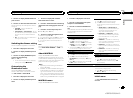
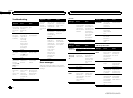
Important
! When installing this unit in a vehicle without
an ACC (accessory) position on the ignition
switch, failure to connect the red cableto the
terminal that detectsoperation of the ignition
key may result in battery drain.
O
N
S
T
A
R
T
O
F
F
ACC position NoACC position
! Use this unit with a 12-volt battery and nega-
tive grounding only. Failure todo so may re-
sult in a fire or malfunction.
! To prevent a short-circuit, overheatingor mal-
function, be sure to follow thedirections
below.
— Disconnect thenegative terminal ofthe bat-
tery before installation.
— Secure thewiring with cableclamps or adhe-
sive tape.Wrap adhesivetape around wiring
that comesinto contact with metalparts to
protect thewiring.
— Placeall cables away frommoving parts,
such asthe shift lever andseat rails.
— Placeall cables away fromhot places, such
as nearthe heater outlet.
— Donot connect theyellow cable tothe battery
by passingit through the holeto the engine
compartment.
— Coverany disconnected cable connectors
with insulatingtape.
— Do notshorten any cables.
— Nevercut the insulation ofthe power cableof
this unitin order to sharethe power with
other devices.The current capacityof the
cable islimited.
— Usea fuse of therating prescribed.
— Never wirethe negative speakercable directly
to ground.
— Neverband together negative cablesof multi-
ple speakers.
! When this unit is on, control signalsare sent
through the blue/white cable. Connect this
cable to the system remote control of anex-
ternal power amp or the vehicle’s auto-anten-
na relay control terminal (max. 300mA
12VDC). If the vehicle is equipped with a
glass antenna, connect it to the antenna
booster power supply terminal.
! Never connect the blue/white cable tothe
power terminal of an external power amp.
Also, never connect it to thepower terminal
of the auto antenna. Doing so may result in
battery drain or a malfunction.
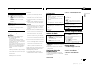
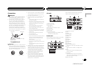
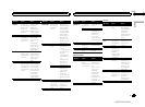
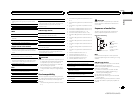
This unit
1
3
2
6 78
4
5
1 Power cord input
2 Microphoneinput
3 Microphone
4m (13ft. 1in.)
4 Rearoutput or subwoofer output
5 Front output
6 Antenna input
7 Fuse (10 A)
8 Wiredremote input
Hard-wired remote control adapter can be
connected (sold separately).
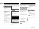
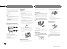
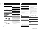
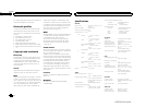
Power cord
Perform these connections when not connect-
ing a rear speaker lead to a subwoofer.
1
8
9
c
d
6
32
4
5
7
a
b
e
f
h
g
LR
F
R
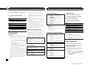
Perform these connections when using a sub-
woofer without the optional amplifier.
1
8
9
c
d
6
32
4
7
a
b
a
b
e
f
h
g
LR
F
SW
i
j
d
c
k l
1 Topower cord input
2 Left
3 Right
4 Front speaker
5 Rearspeaker
6 White
7 White/black
8 Gray
9 Gray/black
a Green
b Green/black
c Violet
d Violet/black
e Black(chassis ground)
Connect to a clean, paint-free metallocation.
f Yellow
Connect to the constant 12 V supplytermi-
nal.
g Red
Connect to terminal controlled by ignition
switch (12 V DC).
h Blue/white
Connect to system control terminal of the
power amp or auto-antenna relay control ter-
minal (max. 300 mA 12 V DC).
i Subwoofer(4W)
English
Installation
17
Section
Installation
En
03
<QRD3123-A/N>17