


E
N
G
L
I
S
H
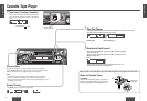
CQ-RG133W
19
CQ-RG133W
18
E
N
G
L
I
S
H
15
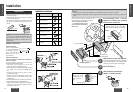
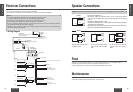
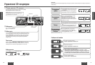
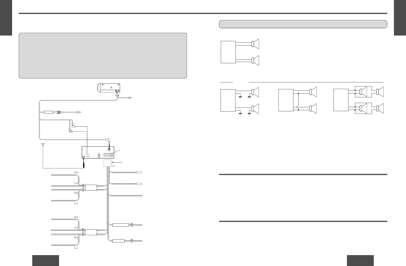
Speaker Connections
Caution: Please follow the instructions given below. Failure to do so will cause damage to the unit and speakers.
L
R
-
-
-
-
-
-
-
-
-
-
+
+
+
+
+
+
+
+
+
+
-
+
-
+
-
+
-
+
-
+
-
+
-
+
-
+
L
R
L
R
L
R
<Right>
<Wrong>
(White)
(White
w/black stripe)
Chassis
(Gray
w/black stripe)
(Gray)
Chassis
• Use ungrounded speaker only.
• The maximum speaker input should be 45 W or more. (If used with the optional
power amplifier, the speaker input should be higher than the maximum amplifier
output.)
• The speaker impedance should be 4 - 8 Ω.
• This unit uses the BTCL circuit, so each speaker should be connected separately
using parallel vinyl insulated cords.
• The speaker cords and the power amplifier unit should be kept away (about 30 cm
apart) from the antenna and antenna extension cord.
• Never connect the speaker cord to
the body of the car.
• Do not use a 3-wire type speaker
system having a common earth
lead.
• Do not connect more than one
speaker to one set of speaker
leads.
Fuse
Use fuses of the same specified rating (15 A). Using different substitutes or fuses with higher ratings, or
connecting the unit directly without a fuse, could cause fire or damage to the unit.
If the fuse replacement fails, contact your nearest authorized Panasonic Service Center.
Maintenance
Your product is designed and manufactured to ensure the minimum of maintenance. Use a soft cloth for
routine exterior cleaning. Never use benzine, thinner, or other solvents.
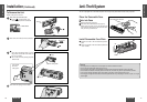
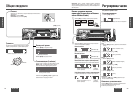
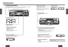
Electrical Connections
CQ-RG133W
Antenna
CD Changer
Control Connector
Battery Lead
To the car battery, continuous
+12V DC
Power Connector
Blue/white stripe
Front speaker lead
White
White/black stripe
Gray
Gray/black stripe
Green
Green/black stripe
Violet
Violet/black stripe
Left
Front
Rear
Right
Right
Left
Rear speaker lead
Blue
Black
Yellow
Red
External amplifier control power lead
Not Used
Ground lead
(To a clean, bare metallic
part of the car chassis.)
Battery lead
(To the car battery,
continuous +12 V DC)
ACC power lead
(To ACC power, +12 V DC)
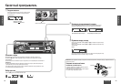
L(White)
R(Red)
CD•C-IN
Fuse(3A)
Extension Cord
(DIN/BATT/RCA/GND)
Ground Lead
To a clean, bare metallic
part of your car
RCA Cord
DIN Cord
(White)
(Red)
(R)
(L)
CD Changer
CX-DP88U
Fuse (15 A)
(option)
Supplied for an optional CD Changer
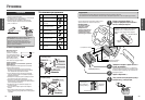
BATTERY
FRONT SP
BATTERY 15A
ACC
REAR SP
Preparation:
• This unit can be connected to an optional CD changer (CX-DP88U).
• For connection to a CD changer, refer to the operating instructions of the CD Changer (CX-DP88U).
Caution:
• This product is designed to operate with a 12 V DC, negative ground battery system.
• To prevent damage to the unit, be sure to follow the connection diagram below.
• Strip about 5mm of the lead ends for connection (only non-ISO connector cords).
• Do not insert the power connector into the unit until the wiring is completed.
• Be sure to insulate any exposed wires from a possible short-circuit from the car chassis. Bundle all cables and
keep cable terminals free from touching any metal parts.
• Remember, if your car has a drive computer or a navigation computer, the data of its memory may be erased when
the battery terminals are disconnected.
❐ Wiring Diagram
E
N
G
L
I
S
H
14