


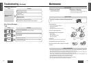
Q’tyItemNo. Diagram
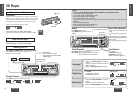
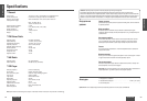
CQ-DP153W
13
CQ-DP153W
12
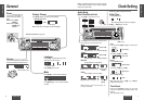
Installation Hardware
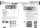
Installation
E
N
G
L
I
S
H
8
E
N
G
L
I
S
H
7
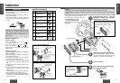
• Before installation, check the radio operation with
antenna and speakers.
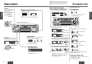
• Disconnect the cable from the negative (–) battery ter-
minal (see caution below).
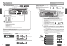
• Unit should be installed in a horizontal position with
the front end up at a convenient angle, but not more
than 30°.
Dashboard Installation
Installation Opening
The unit can be installed
in any dashboard having
an opening as shown at
right. The dashboard
should be 4.5 mm - 6 mm thick in order to be able to
support the unit.
Installation Precautions
This product should be installed by a professional
installer, if possible.
In case of difficulty, please consult your nearest author-
ized Panasonic Service Center.
1. This system is to be used only in a 12-volt, DC bat-
tery system (car) with negative ground.
2. Follow the electrical connections carefully (
a page
16). Failure to do so may result in damage to the
unit.
3. Connect the power lead (red) after all other connec-
tions are made.
4. Be sure to connect the battery lead (yellow) to the
positive terminal (+) of the battery or fuse block
(BAT) terminal.
5. Insulate all exposed wires to prevent short circuiting.
6. Secure all loose wires after installing the unit.
7. Please carefully read the operating and installation
instructions of the respective equipment before con-
necting it to this unit.
Preparation
30˚ or less
Caution: Do not disconnect the battery terminals of
a car with trip or navigational computer since all
user settings stored in memory will be lost.
Instead take extra care with installing the unit to
prevent shorts.
182 mm
53 mm
Fire Wall of Car
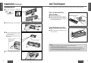
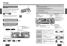
w Hex. Nut
e Rear Support Strap
t Mounting Bolt
q Mounting Collar
r Tapping Screw
3 mmø
(a) Using the Rear Support Strap
Rubber Cushion
(Option)
t Mounting Bolt
q Mounting Collar
Rear Support Bracket
(Provided on the car)
(b) Using the Rubber Cushion (option)
1
2
3
4
Cautions:
• We strongly recommend that you wear gloves for installation work to protect yourself from injuries.
• When bending the mounting tab of the mounting collar with a screwdriver, be careful not to injure your hands and
fingers.
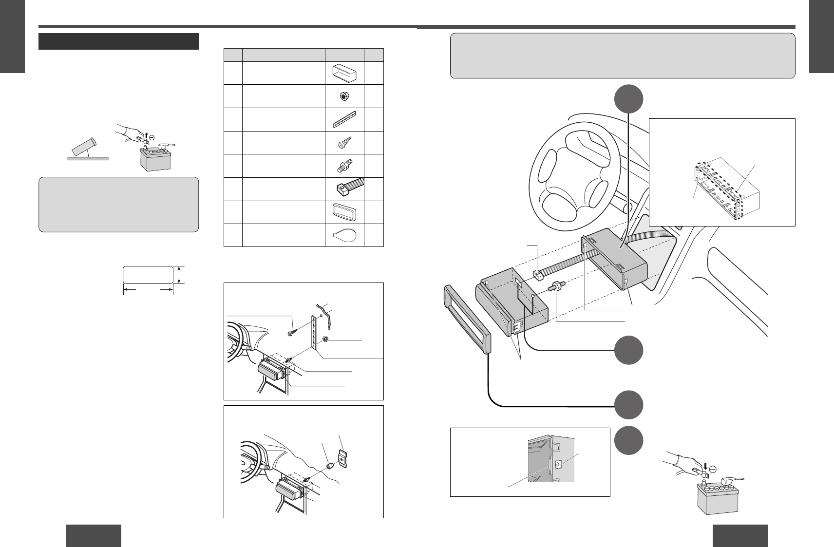
Establish the rear connection of the unit.
After fixing Mounting Bolt t and Power Connector
y, fix the rear of the unit to the car body by either
method (a) or (b) shown on the previous page.
Insert Trim Plate u.
After installation reconnect the nega-
tive (–) battery terminal.
First complete the electrical connections, and
then check them for correctness.(
a page 16)
Insert Mounting Collar q into the
dashboard, and bend the mounting
tabs out with a screwdriver.
The included Mounting Collar
q is designed specially for this
unit. Do not use it to attach any
other model.
y Power Connector
Engage the both sides
Mounting Springs (
C)
in the mounting holes
of the Mounting Collar
q firmly.
Mounting Spring
Mounting
Hole
Tab
q Mounting
Collar
Mounting Springs (C)
Mounting Holes
t Mounting Bolt
The tabs to be bent vary depending on the car.
To securely install the unit, fully bend a num-
ber of the tabs so that there is no rattling.
Example:
q
1
1
1
1
1
1
1
2
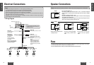
Mounting Collar
Hex. Nut (5 mmø)
Rear Ssupport Strap
Tapping Screw
(5 mmø
× 16 mm)
Mounting Bolt (5 mmø)
Power Connector
Trim Plate
Dismounting Plate
w
e
r
t
y
u
i