


5
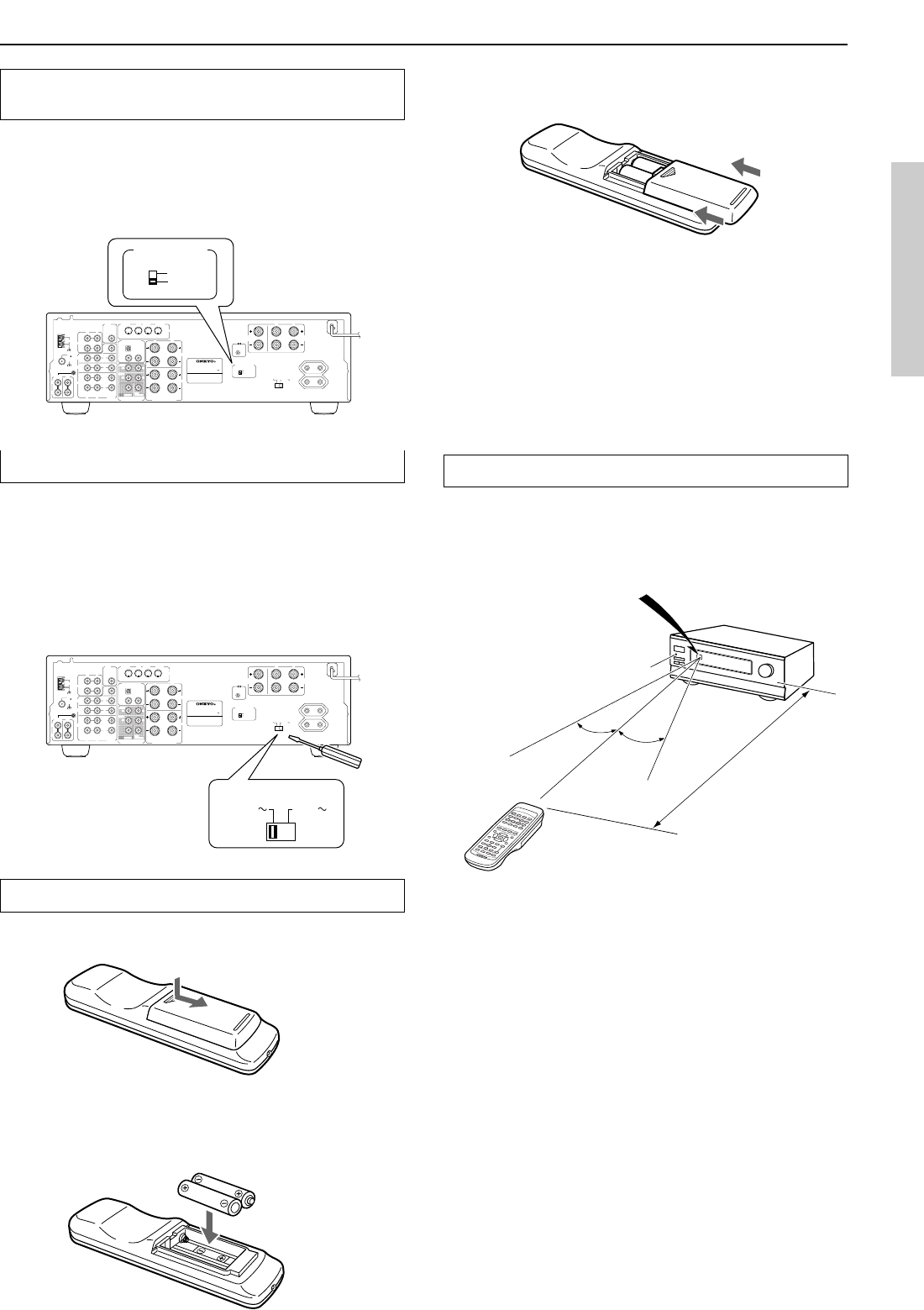
3. After batteries are installed and seated correctly,
replace the compartment cover.
Notes:
• Do not mix new batteries with old batteries or different kinds
of batteries.
• To avoid corrosion, remove the batteries if the remote
controller is not to be used for a long time.
• Remove dead batteries immediately to avoid damage from
corrosion. If the remote controller does not operate smoothly,
replace both batteries at the same time.
• The life of the batteries supplied is about six months but this
will vary depending on usage.
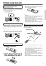
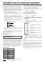
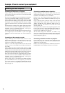
Using the remote controller
Point the remote controller toward the remote control sensor. The
STANDBY indicator lights up when the unit receives a signal
from the remote controller.
Notes:
• Place the unit away from strong light such as direct sunlight or
inverted fluorescent light which can prevent proper operation
of the remote controller.
• Using another remote controller of the same type in the same
room or using the unit near equipment which uses infrared rays
may cause operational interference.
• Do not put objects on the remote controller. Its buttons may be
pressed by mistake and drain the batteries.
• Make sure the audio rack doors do not have colored glass.
Placing the unit behind such doors may prevent proper remote
controller operation.
• If there is any obstacle between the remote controller and the
remote control sensor, the remote controller will not operate.
Installing batteries into the remote controller
1. Remove the battery compartment cover by
pressing and sliding the cover.
2. Insert two AA (R6 or UM-3) batteries into the
battery compartment. Carefully follow the
polarity diagram (positive (+) and negative (–)
symbols) inside the battery compartment.
Before using this unit
Remote control sensor
STANDBY indicator
TX-DS494
Approx. 5 meters
(16 feet)
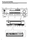
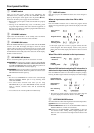
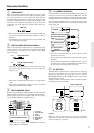
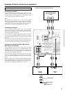
Setting the AM tuning step frequency
(Worldwide models only)
Worldwide models are equipped with a switch that controls the
AM band tuning steps. Please set this switch to match the AM
band tuning step frequency in your area.
U.S.A. and Canada: 10 kHz
Other areas: 9 kHz
30°
30°
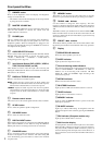
Setting the voltage selector (Worldwide models only)
Worldwide models are equipped with a voltage selector to
conform with local power supplies. Be sure to set this switch to
match the voltage of the power supply in your area before
plugging in the unit.
Determine the proper voltage for your area: 220-230 V or 120 V. If
the preset voltage is not correct for your area, insert a screwdriver
into the groove in the switch. Slide the switch all the way to the
right (120 V) or to the left (220-230 V), whichever is appropriate.
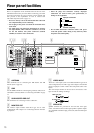
ANTENNA
FM
75
AM
REMOTE
CONTROL
CENTER
SPEAKER
SURROUND
SPEAKERS
R
L
IN
IN IN
L
L
R
R
FRONT
CENTER
SURR
SUB
WOOFER
RL
1
2
COAXIAL
CAUTION:
SPEAKER IMPEDANCE
6 OHMS MIN. PER EACH
SPEAKER TERMINAL
OUT
IN
A
B
R
L
FRONT
SPEAKERS
R
L
R
L
IN
OUT
VIDEO
DIGITAL
INPUT
MONITOR
OUT
S
VIDEO
DVD
VIDEO
1
VIDEO 2
PHONO
CD
SUB
WOOFER
PRE OUT
TAPE
DVD
VIDEO 2
VIDEO 1
R
L
OPTICAL
IN
IN
MULTI
CHANNEL INPUT
MONI-
TOR
OUT
GND
120
V
VOLTAGE SELECTOR
220-230
V
SWITCHED
TOTAL 100W MAX.
AC OUTLETS
AV RECEIVER
MODEL NO.
TX-DS494
RATING:
50
/
60
Hz 260
W
AC 120
/
220
-230
V
10
k
Hz
9
k
Hz
AM FREQUENCY
STEP
10
k
Hz
9
k
Hz
AM FREQUENCY
STEP
ANTENNA
FM
75
AM
REMOTE
CONTROL
CENTER
SPEAKER
SURROUND
SPEAKERS
R
L
IN
IN IN
L
L
R
R
FRONT
CENTER
SURR
SUB
WOOFER
RL
1
2
COAXIAL
CAUTION:
SPEAKER IMPEDANCE
6 OHMS MIN. PER EACH
SPEAKER TERMINAL
OUT
IN
A
B
R
L
FRONT
SPEAKERS
R
L
R
L
IN
OUT
VIDEO
DIGITAL
INPUT
MONITOR
OUT
S
VIDEO
DVD
VIDEO
1
VIDEO 2
PHONO
CD
SUB
WOOFER
PRE OUT
TAPE
DVD
VIDEO 2
VIDEO 1
R
L
OPTICAL
IN
IN
MULTI
CHANNEL INPUT
MONI-
TOR
OUT
GND
120
V
VOLTAGE SELECTOR
220-230
V
SWITCHED
TOTAL 100W MAX.
AC OUTLETS
AV RECEIVER
MODEL NO. TX-DS494
RATING:
50
/
60
Hz 260
W
AC 120
/
220
-230
V
10
k
Hz
9
k
Hz
AM FREQUENCY
STEP
120
V
VOLTAGE SELECTOR
220-230
V