


FIG.11
+
-
-
+
POWER SUPPLY
The side label,
shows the type
and value of the
power supply.
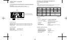
OUTPUTS / SALIDAS
mA Vdc
INPUT / ENTRADA
SUPPLY / ALIMENTACION
3 4 5 6
9 10 11 12
7
1
+
Lo
H i
+--
The voltage excitation for the current loop, it
is supplied by the signal conditioner (24 Vdc
@ 25 mA).
Terminals 3 and 5, for 2-wire transducers.
Terminals 3, 5 and 6 for 3-wire transducers.
Current generator signal
-
Transducer
2-wire system
+
Transducer
3-wire system
signal
FIG.3
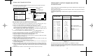
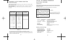
Solder pads are used to change the value of the power supply. They
are located on the "MA" Power Supply module, on the solder side, Fig.
4.
See Table 1 for more details.
TABLE 1
* Using the transformer code 63338301 and selecting the
solder pads as indicated.
** Using the power supply option, code 029103 and select-
ing the solder pads as indicated.
Power Status of the solder pads
supply Closed Opened
220 Vac 3,3 and 1 2 and 2
110 Vac 3,3,2 and 2 1
*48 Vac 3,3 and 1 2 and 2
*24 Vac 3,3,2 and 2 1
**24 Vdc 1 3,3,2 and 2
The power supply must be connected to Terminals 1 and 7.
The characteristics of the power supply are shown on the side
label.
WARNING.- If the power supply is dc voltage, be careful with
the polarity indicated for each terminal.
Make sure the signal conditioner is correctly connected to a
power supply of the correct voltage and frequency. Do not use any
other power supply. Permanent damage may result to the signal
conditioner.
PRECAUTIONS.- The installation must incorporate safety
devices to protect the operator and the process when using the
signal conditioner to control a machine or process where injury to
personnel or damage to equipment or process, may occur as a
result of failure of the signal conditioner.
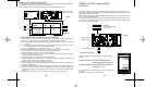
CHANGING THE POWER SUPPLY
FIG.4
Module MA
Solder view
3
3
1
2
2
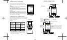
OUTPUTS / SALIDAS
mA Vdc
INPUT / ENTRADA
SUPPLY / ALIMENTACION
3 4 5 6
9 10 11 12
7
1
+
Lo
H i
+
-
-
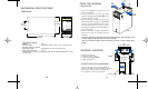
POWER SUPPLY module MA
Vexc
+
_
LOAD LOAD
WIRING CONNECTIONS
POWER SUPPLY
The side label,
shows the type
and value of the
power supply.
OUTPUTS / SALIDAS
mA Vdc
INPUT / ENTRADA
SUPPLY / ALIMENTACION
3 4 5 6
9 10 11 12
7
1
+
Lo
H i
+
-
-
≤ 1 V
↑
↑
↓
> 1 V
↓
FIG.10
+
-
Vexc
+
_
LOAD LOAD
CCT-55-V
CCT-55-I
413