


A B C
D
A
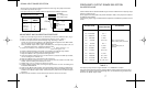
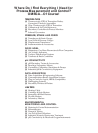
INPUT Close jumpers on module :
RANGE MP ME
"MP" Input board
Components
view
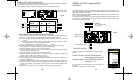
SIGNAL INPUT RANGE SELECTION
Set the jumper to the position indicated in the table below for each range. The jumpers are located
on the "MP" input board and "ME" input module. See Fig. 9.
If the signal input range is modified, follow the adjustment and calibration procedure.
TABLE 7
FIG.9
5
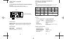
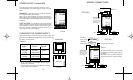
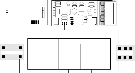
SIGNAL OUTPUT module MS-55
OVERVIEW
This module contains all the components for the frequency generator, and the trimmer for the
Span coarse frequency, The jumpers and solder pads to select the output range frequency and
solder pad to select the pulse width.
Both models are delivered as a standard version, with the frequency output adjusted from 0 to
4 KHz., unless specified otherwise.
The frequency range can be set in pulses per second (12 different ranges, see table 2) or in
pulses per hour (13 different ranges, see table 3), using the jumpers and solder pads located
on the MS-55 module, see figure 5.
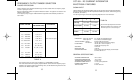
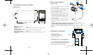
OUTPUTS / SALIDAS
mA Vdc
INPUT / ENTRADA
SUPPLY / ALIMENTACION
3 4 5 6
9 10 11 12
7
1
+
Lo
H i
+--
FIG.6
D C B A
E
FIG.5
The signal conditioner provides two different types of output
pulses.
Pulses in Current: 100 mA. (24 Vdc external
power supply), terminals 9 - 10
Pulses in Voltage: 24 Vdc. @ 20 mA maximum,
terminals 11 - 12
Do not use both outputs simultaneously. Only one selection can
be made.
The side label shows which one is selected.
TYPES OF PULSES
SPAN coarse gain (P3)
Solder pad 2
Solder pad 1
JUMPERS
on components side.
Snap-on type
J4
"ME" Input module
Components view
0 to 5mAdc A & D --------
0 to 20 mAdc D C
4 to 20 mAdc D A & C
0 to 50 mAdc D -------
ADJUSTMENT AND CALIBRATION PROCEDURE
1. When input and output signal values are determined, remove the conditioner case. (Fig. 1).
2. Check on the "MA" module, if the selected power supply is correct. (Table 1).
3. Select on the "MP" input board and "ME" input module the desired Current range, according
to Table 7.
Close on "MS-55" output module, jumper E & solder pad 1, and open the jumpers A, B, C &
D and solder pads 2 & 5, according to Tables 2 and 3.
4. Connect the calibrator to the conditioner terminals 5 and 6.
5. Connect a digital voltmeter, to the jumper "J4" located on the "MS-55 output module.
6. Power up the signal conditioner with the appropriate power supply.
7. Adjust the calibrator until it generates the low signal level.
8. Check the voltmeter reading is 0. If not, turn the trimmer P1, located on the "ME" input module,
until the reading of the voltmeter is 0.
9. Adjust the calibrator until it generates the high signal level.
10. Check the voltmeter reading is 10.00 V. If not, turn the trimmer P2, located on the "ME" input
module, until the reading of the voltmeter is 10.00 V.
11. Repeat steps 7 thru 10, until the two values are correct.
12. Connect a digital frequency meter, to the signal output terminals 11 and 12. The reading must
be between 2500/5000 Hz.
13. Select on the "MS-55" output module, the corresponding jumpers, according to Tables 2 & 3.
14. Adjust the calibrator until it generates the high signal level and turn the SPAN trimmer (P3),
located on the "MS-55" output module, until the frequency meter shows the desired output
frequency.
15. Disconnect the conditioner and the instruments used and reinsert into the case.
Solder pad 5
12