


TFA9810_3 © NXP B.V. 2008. All rights reserved.
Product data sheet Rev. 03 — 20 February 2008 20 of 29
NXP Semiconductors
TFA9810
Audio amplifier 2 x 12 W
• R
L
= load resistance [Ω].
• R
DSon
= drain-source on-state resistance [Ω].
• R
s
= series resistance [Ω].
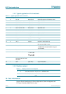
Example:
A 4 Ω speaker in BTL configuration can be used up to a supply voltage of 12 V without
running into current limiting. Current limiting (clipping) will avoid audio holes, but it causes
a sound distortion similar to voltage clipping.
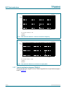
14.3 Speaker configuration and impedance
For a flat-frequency response (second-order Butterworth filter) it is necessary to change
the low-pass filter components L
LC
and C
LC
according to the speaker configuration and
impedance. Table 12 shows the practical required values:
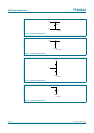
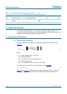
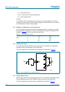
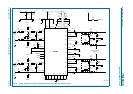
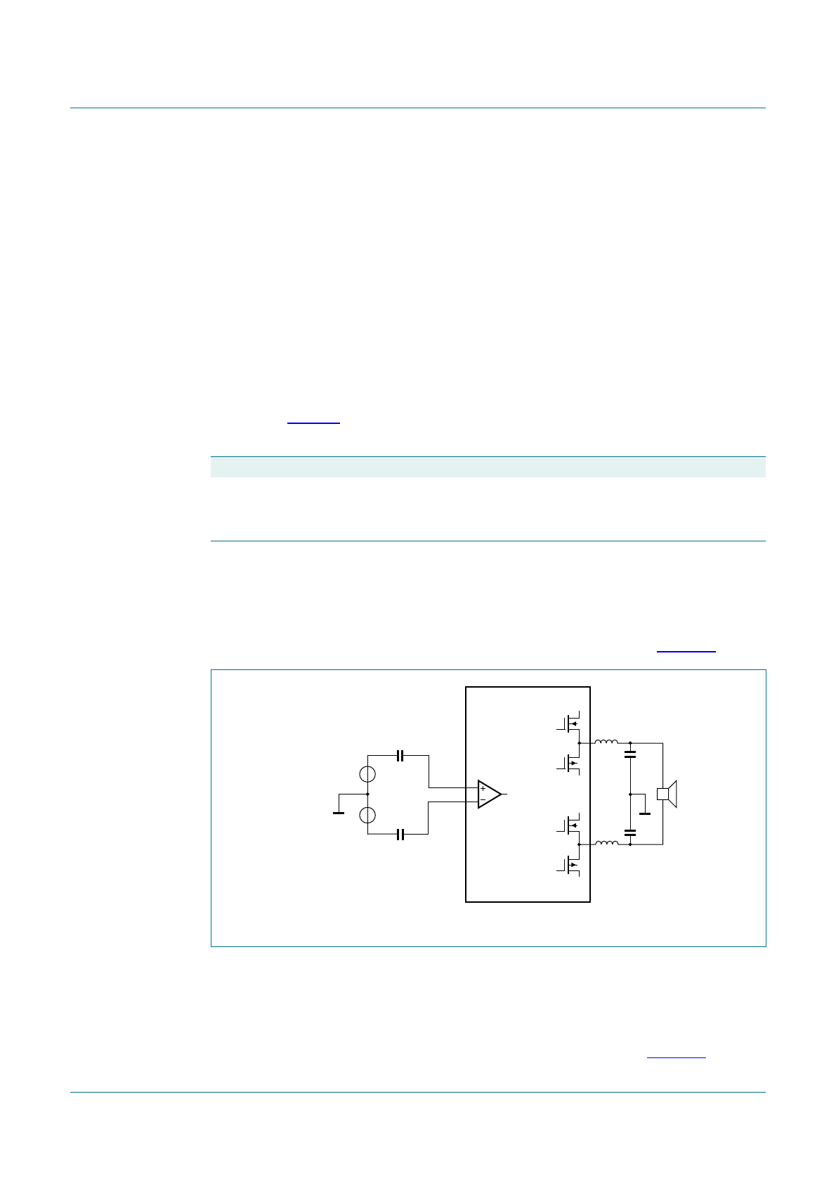
14.4 Differential input
For a high common-mode rejection ratio and a maximum of flexibility in the application,
the audio inputs of the application are fully differential.
The input configuration for a differential-input application is illustrated in Figure 28.
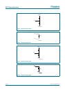
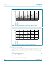
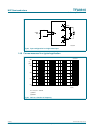
14.5 Single-ended input
When using an audio source with a single-ended ‘out’, it is important to connect the IN1N
from the application board to the VSS/GND of the audio source (e.g. Audio DSP).
The input configuration for single-ended ‘in’ application is illustrated in Figure 29.
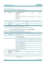
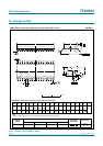
Table 12. Filter component values
Configuration Impedance [Ω] L
LC
[µF] C
LC
[nF]
BTL 4 10 1500
6 16 1000
8 22 680
Fig 28. Input configuration for differential input
IN1P
IN1N
AUDIO
DSP
OUT1P
OUT1N
010aaa021
+
−
V
SS