


TFA9810_3 © NXP B.V. 2008. All rights reserved.
Product data sheet Rev. 03 — 20 February 2008 17 of 29
NXP Semiconductors
TFA9810
Audio amplifier 2 x 12 W
[1] High-side and low-side power switch have the same series resistance.
[2] Output power measured across the loudspeaker load. Output power is measured indirectly via R
DSon
.
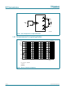
12.3 AC characteristics measured in a typical application
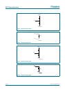
t
resp
response time transition PWM output from
LOW to HIGH
V
I
= 70 mV
V
I
= 3.3 V
-
-
60
50
-
-
ns
ns
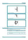
transition PWM output from
HIGH to LOW
V
I
= 70 mV
V
I
= 3.3 V
-
-
60
50
-
-
ns
ns
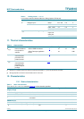
t
w(min)
minimum pulse width PWM output - 60 - ns
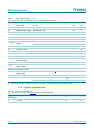
R
DSon
drain-source on-state
resistance
[1]
- 0.28 0.35 Ω
η
po
output power
efficiency
output power 2x9Winto 8 Ω.
P
o
= P
o(nom)
[2]
87 89 - %
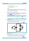
Table 10. Dynamic characteristics
…continued
T
amb
= 25
°
C; V
P
= 12 V; R
L
= 8
Ω
; Figure 33 unless otherwise specified.
Symbol Parameter Conditions Min Typ Max Unit
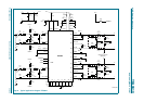
Table 11. AC characteristics measured in typical application
T
amb
= 25
°
C; V
P
= 12 V; R
L
= 8
Ω;
f
osc
= 550 kHz; Figure 33 unless otherwise specified.
Symbol Parameter Conditions Min Typ Max Unit
V
P
supply voltage V
P
= V
DDPx
− V
SSPx
8 1220V
P
o(RMS)
RMS output power R
L
= 8 Ω; V
P
= 12 V;
THD = 10 %; Two channel
driven; no heat sink required.
- 9.5 - W
P
o
output power V
P
= 12 V; R
L
= 8 Ω
THD = 10 % 8.5 9.5 - W
THD = 1 % 6.5 7.5 - W
V
P
= 14 V; R
L
= 8 Ω;
THD = 10 %; thermally limited
-12-W
V
P
= 16 V; R
L
= 8 Ω;
THD = 10 %; thermally limited
-15-W
V
P
= 12 V; R
L
= 6 Ω;
THD = 10 %; thermally limited
-12-W
V
P
= 12 V; R
L
= 4 Ω;
THD = 10 %; thermally limited
-15-W
THD+N total harmonic
distortion-plus-noise
P
o
is 1 W; f = 1 kHz; AES17
brick-wall filter
- 0.04 0.1 %
η
po
output power
efficiency
P
o
= 9 W 87 89 - %
G
v(cl)
closed-loop voltage
gain
V
I
= 100 mV (RMS); f
i
= 1 kHz 19 19.7 21 dB
V
n(o)
output noise voltage Inputs shorted;
AES17 brick-wall filter
- 150 - µV