


TFA9810_3 © NXP B.V. 2008. All rights reserved.
Product data sheet Rev. 03 — 20 February 2008 16 of 29
NXP Semiconductors
TFA9810
Audio amplifier 2 x 12 W
[1] Current limiting concept: in overcurrent condition no interruption of the audio signal in case of impedance drop.
12.2 Dynamic characteristics
I
I
input current V
I
= 5 V - 1 20 µA
SO/OL input
V
IL
LOW-level input voltage with respect to V
SSD
- - 0.4 V
V
IH
HIGH-level input voltage with respect to V
SSD
3 4 4.5 V
STABI
V
STABI
voltage on pin STABI with respect to V
SS
10 11 12 V
Comparator full-differential input stage
V
offset(i)(eq)
equivalent input offset
voltage
--1mV
20 Hz < f < 20 kHz - - 15 µV
V
cm
common mode voltage V
SSA
+ 3 - V
DDA
−1V
I
IB
input bias current - - 1 µA
OverTemperature Protection (OTP)
T
prot
protection temperature 150 - - °C
OverVoltage Protection (OVP)
V
th(ovp)
overvoltage protection
threshold voltage
level internal fixed 20 21.5 23 V
UnderVoltage Protection (UVP)
V
P(uvp)
undervoltage protection
supply voltage
level internal fixed 7 7.5 8 V
OverCurrent Protection (OCP)
I
O(ocp)
overcurrent protection
output current
[1]
3 3.5 - A
Window Protection (WP)
V
O
output voltage high level - V
DDA
− 1- V
low level - V
SSA
+ 1 - V
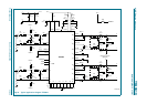
Table 9. Static characteristics
…continued
T
amb
= 25
°
C; V
P
= 12 V; f
osc
= 550 kHz; Figure 33 unless otherwise specified
Symbol Parameter Conditions Min Typ Max Unit
Table 10. Dynamic characteristics
T
amb
= 25
°
C; V
P
= 12 V; R
L
= 8
Ω
; Figure 33 unless otherwise specified.
Symbol Parameter Conditions Min Typ Max Unit
PWM output
t
r
rise time - 10 - ns
t
f
fall time - 10 - ns