


15
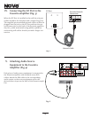
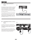
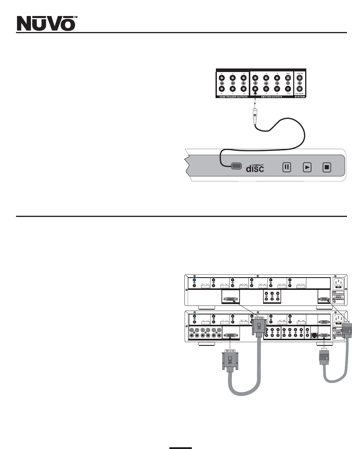
VI. Connecting the IR Emitters
(Fig. 5)
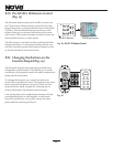
IR commands for the source equipment are transferred
from the Essentia amplifier to the source equipment
via mini IR mouse emitters. Six of these are supplied
with your Essentia System. The emitter is plugged
into the corresponding source IR output on the
Essentia and then placed over the IR receiver window
on the source component. The IR outputs are individu-
ally routed to sources 1-6.
The two SUM outputs will flash any IR command that
is sent from any of the zones. This is used to connect
the NuVo T3 Tuner to the Essentia System or an IR
blaster designed to flash IR commands to a variety of
components. This is done by plugging a single mono
1/8" patch cable into the SUM IR output and into the
Direct IR input on the T3.
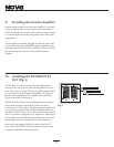
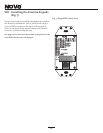
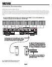
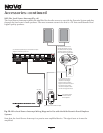
VII. Expanding Essentia to 12 Zones
(Fig. 6)
Six additional listening zones can be added to the
Essentia System using the Essentia Expander package.
The expansion is easily done using the Source Link
and Digital Link multi-pin outputs on the Essentia
main amplifier.
The necessary cables for this are supplied with the
Expander package. No other connections are necessary
with the exception of the AC power cord and the addi-
tional speaker terminations. The additional Cat-5
wires for the zones 7-12 plug into the EZ Port.
Fig. 5
Fig. 6
R
ZONE 6
SYSTEM
ZONE TRIGGEROUTPUTS
SOURCE LINK
SOURCE INPUTS
ZONE 1
NETWORK
EMITTER OUTPUTS
DIGITALLINK
ZONE 3
ZONE 4
ZONE 5
ZONE 2
PROGRAM
RS-232
CONNECT TO
NV-I8X
USE NV-SLC1
CABLE
CONNECT TO
NV-I8EZP1
USE NV-NC1
CABLE
SYS ON
EXT.MUTE
SUM1
1
1
2
3
123
4
5
6
SUM2
5
45
6
CONNECT TO
NV-I8X
USE NV-SLC1
CABLE
12345
6
12345
6
OUTPUT POWER
OUTPUT POWER
OUTPUT POWER
OUTPUT POWER
OUTPUT POWER
OUTPUT POWER
20W/6OHM X2
20W/6OHM X2
20W/6OHM X2
20W/6OHM X2
20W/6OHM X2
20W/6OHM X2
VARIABLE
OUTPUT
VARIABLE
OUTPUT
VARI ABLE
OUTPUT
VARI ABL E
OUTPUT
VARI ABLE
OUTPUT
VARI ABLE
OUTPUT
FIXED
OUTPUT
FIXED
OUTPUT
FIXED
OUTPUT
FIXED
OUTPUT
FIXED
OUTPUT
FIXED
OUTPUT
TIP=L
RING=R
TIP=L
RING=R
TIP=L
RING=R
TIP=L
RING=R
TIP=L
RING=R
TIP=L
RING=R
R
ZONE 12
ZONE TRIGGEROUTPUTS
SOURCE LINK
ZONE 71
DIGITALLINK
ZONE 9
ZONE 10
ZONE 11
ZONE 8
CONNECT TO
NV-I8X
USE NV-SLC1
CABLE
1
7
8
9
5
10 11
12
CONNECT TO
NV-I8X
USE NV-SLC1
CABLE
OUTPUT POWER
OUTPUT POWER
OUTPUT POWER
OUTPUT POWER
OUTPUT POWER
OUTPUT POWER
20W/6OHM X2
20W/6OHM X2
20W/6OHM X2
20W/6OHM X2
20W/6OHM X2
20W/6OHM X2
VARIABLE
OUTPUT
VARIABLE
OUTPUT
VARIABLE
OUTPUT
VARI ABLE
OUTPUT
VARIABLE
OUTPUT
VARIABLE
OUTPUT
FIXED
OUTPUT
FIXED
OUTPUT
FIXED
OUTPUT
FIXED
OUTPUT
FIXED
OUTPUT
FIXED
OUTPUT
TIP=L
RING=R
TIP=L
RING=R
TIP=L
RING=R
TIP=L
RING=R
TIP=L
RING=R
TIP=L
RING=R