


-
-
+
+
LEFT
RIGHT
LEFT
RIGHT
8
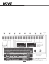
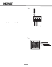
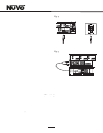
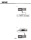
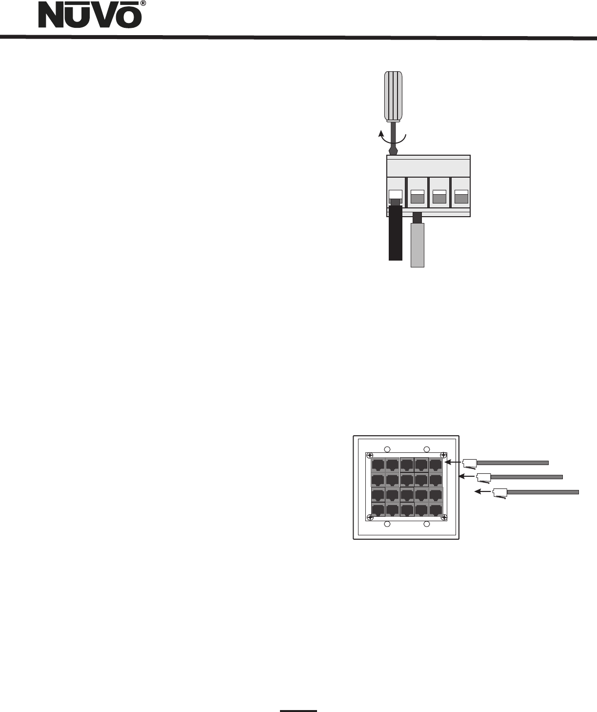
II. Terminating the Speaker Wire (Fig. 2)
All the NuVo systems operate across a homerun wiring
scheme using CAT5 for the zone Control Pad control
communication, and a separate run of speaker wire for each
zone from the speaker outputs to the zone speakers. We
suggest 16 AWG 2 or 4-conductor speaker wires.
The speaker wire termination is done using a modular Euro
connector. Each conductor is screwed down to the connector
block and plugged into the appropriate speaker output on
the back of the amplifier. The proper termination is Left
channel: – and +; Right channel: – and +.
Fig. 2
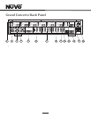
III. Installing the Grand Concerto Amplifier
System setup works best when the amplifier is placed in the
same location as the audio source equipment. This is
typically in an audio rack, entertainment center, or a closet
dedicated to housing the home audio/video equipment.
The amplifier should be plugged in and the power button on
the front panel should be engaged before proceeding with
the rest of the installation. This activates the internal
protective circuitry of the Grand Concerto System.
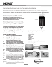
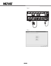
IV. Installing the NV-I8GEZP EZ Port (Fig.3)
The EZ Port is a multi-connection hub designed to accept all
the CAT5 wires from the keypads in the system. The location
of the EZ Port should be determined by the location of the
Grand Concerto amplifier. It is best to place in a wall behind
the amplifier that would be easily accessible if necessary.
The EZ Port fits easily in most dual-gang size, low-voltage
ring with an open back. These are often referred to as mud
rings . Simply plug the terminated CAT5 wires into any of
the 20 available jacks on the back of the EZ Port. The order in
which the individual CAT5 wires are plugged in is not
important, although it is strongly recommended that you
label the CAT5 with the appropriate zone number for future
reference.
Once you have plugged the CAT5 wires into the EZ Port, screw
the EZ port into its construction bracket using the supplied
mounting screws.
Fig. 3