


Revision 1.0 Page 6 of 25
User Guide
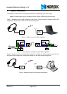
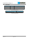
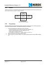
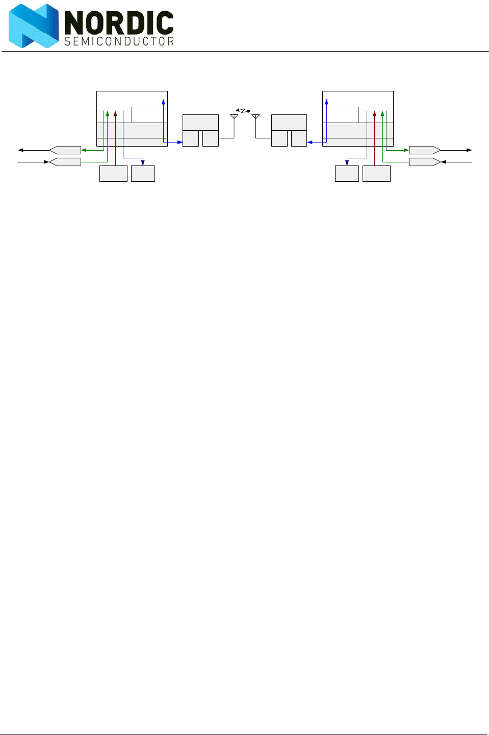
Figure 4. System diagram of headset unit with audio dongle configuration
The headset unit and the audio dongle are based on the same hardware. Both use an audio codec to pro-
vide coding and decoding of the analog audio signals to 16-bit linear PCM code. This bit stream is pro-
cessed by the micro controller to an 8-bit a-law bit stream, which is sent to the nRF24L01 for wireless
transmission. The nRF24L01 uses the ShockBurst feature to transmit and receive the RF packets in a time
multiplexed scheme. The micro controller fetches received 8-bit a-law samples from the nRF24L01, con-
verts to 16-bit linear PCM, and outputs to the audio codec. Button status is read by the MCU and embed-
ded in the RF packets.
The USB Dongle uses a USB Audio Controller to handle the USB interface. The audio samples are 16 bit
linear PCM between the USB Audio Controller and the micro controller, where the micro controller acts as
a bus master. The audio frame signals are derived from clock output from the USB Audio Controller to
keep the audio frames in sync with the USB audio frames. The micro controller can also access the USB
HID interface through the I2C bus, also with the micro controller as the bus master. The USB HID interface
is used to upstream button status received from the headset to the USB host. The micro controller converts
the 16 bit linear PCM code to an 8-bit a-law bit stream, which is sent to the nRF24L01 for wireless trans-
mission. The nRF24L01 uses the ShockBurst feature to transmit and receive the RF packets in a time mul-
tiplexed scheme.
DAC
ADC
MCU
Voice
Protocol
I/O
I/O
PHY
RF
ShockBurst
ButtonsLED
Application
Audio
Out
Audio
In
DAC
ADC
MCU
Voice
Protocol
I/O
I/O
PHY
RF
ShockBurst
Buttons LED
Application
Audio
Out
Audio
In