


Revision 1.0 Page 19 of 25
Headset Reference Design v1.0
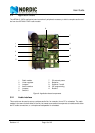
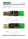
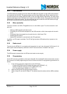
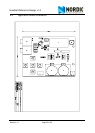
4.2 USB dongle
4.2.1 Antenna
The USB Dongle uses a PCB quarter wave antenna. The USB Dongle is production ready, and any modi-
fications to the antenna are only required as part of the antenna tuning process to compensate for plastic
housing, and so on.
If you want an antenna redesign, any 50 ohm 2.4GHz antenna can be used, from an inexpensive PCB
antenna to space saving chip antennas.
There are different types of PCB antennas, from inverted F antennas to simple quarter wave antennas.
You must know the characteristics of the chosen antenna and implement it as required. Tuning the
antenna will be necessary because an antenna’s impedance and performance are affected by the environ-
ment the antenna is used in.
Using a chip antenna must only be done according to the chip antenna vendors recommendations.
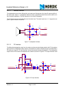
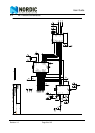
The USB Dongle is equipped with the recommended antenna matching network layout for the nRF24L01
and a PCB quarter wave antenna. If a different antenna is going to be used it is important to tune the
antenna matching network to match the impedance at the antenna’s terminal. Another important task of
the antenna matching network is to suppress spurious energy. This can be achieved by following our White
Paper named “Tuning_the_nFR24xx_matching_network” available on our website www.nordicsemi.no
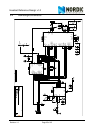
4.2.2 MCU
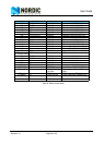
A replacement of the MCU must fulfill these requirements:
• 8-bit MCU
• 6 MHz clock frequency
• 1 to 2 cycles per instruction
• 4bytes E2PROM Memory (can be external)
• 1kbyte of IRAM (can maybe work with 512kbytes)
• 8kbyte program memory (possible to get down to 5 to 6kbytes)
• One Double buffered, synchronous hardware SPI both on RX and TX -or- Ideally I2S interface
• One SPI port for RF and codec
• One two wire interface to USB Audio Controller for call control (open drain type)
• Watchdog times for power management
• One 16-bit timer (Master sync clock)
• One 8-bit timer (hardware sync clock)
• 1.9 to 3.6V supply voltage
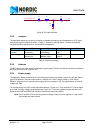
4.2.3 Crystals
The crystal used as the RF crystal is a 16 MHz crystal. Any replacement of this crystal must fulfill the crys-
tal requirements found in the nRF24L01 Product Specification.
The MCU crystal fulfills the requirements given by the MCU. The frequency must be 6.0 MHz in order to
get the timing correct. Any replacements must follow these requirements.