


Revision 1.0 Page 13 of 25
Headset Reference Design v1.0
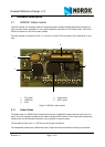
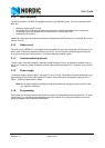
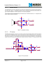
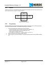
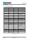
3.2.5 Buttons
There are five buttons on the application board and these are connected to the AVR micro controller on the
radio module as shown in Figure 10. ”Button mapping”.
Figure 10. Button mapping
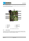
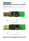
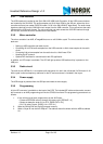
3.2.6 Programming
The radio module can be programmed through the 6-pin ISP connector (P1) with an AVR programming
tool like the STK500 from Atmel. The programming procedure is as follows:
1. If the unit has never been programmed, set the AVR fuses:
• Preserve EEPROM memory through chip erase cycle; [EESAVE = 0]
• Brown-out detection level at Vcc=1.8V; [BODLEVEL=110]
• Clock output on PORTB0; [CKOUT=0]
• Ext.Crystal Osc. Frequency 3.0 - 8.0MHz; [CKSEL=1101 SUT=11]
2. Write the SW hex file into the AVR program memory.
3. Write a 3-byte ID into the AVR EEprom. The address should be written with the MSB at address
00.
SW1
AVR pin 23
SW2
AVR pin 24
SW3
AVR pin 25
SW4
AVR pin 26
SW2
AVR pin 27