


Revision 1.0 Page 12 of 25
User Guide
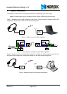
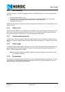
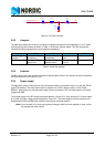
Figure 9. PC output interface
3.2.2 Jumpers
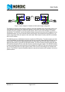
The application board can be set up to interface a headset microphone and loudspeaker, or a PC audio
outlet by placing the jumpers as shown in Table 3. ”Audio filter settings” below. The filter components
mounted should be appropriate for most headset loudspeakers.
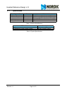
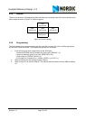
Table 3. Audio filter settings
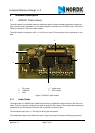
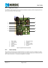
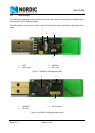
3.2.3 Antenna
The RF output of the radio module is matched to approximately 50 ohm. An antenna must be connected to
the SMA connector to set up an RF link.
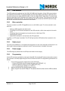
3.2.4 Power supply
The application board is fitted with two coin-cell battery holders, connected in series, for use with ZinkAir
(type 675) batteries. The board also contains a footprint for a CR2 Li battery holder (1/2 AA, Bulgin
BX0031). Alternatively, an external power supply can be connected to P3. You select battery or external
voltage with SW6.
The voltage supply to the RF module should be between 1.9 and 3.6 V. If the onboard 2.5 V linear regula-
tor is used, the input voltage should be between 3 and 15 V. The linear regulator can be switched on or
bypassed with SW7 and SW8 (both switches should have the same position).
Note: Do not exceed 3.6 V when using external voltage unless the linear regulator is used, as this
can damage the radio module.
CJ2 CJ3 W1 W2
Connecting to
headset
Connect to headset
microphone.
Connect to headset
loudspeaker
Mount jumpers 4
and 5
Mount jumper 2.
Connecting to PC Connect to PC micro-
phone input
Connect to PC loud-
speaker output
Mount jumpers 1,
2 and 3
Mount jumper 1.
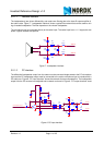
R1
1k
R2
47
C1
2.2u
C2
2.2u
PC loudspeaker out AIN