I Design
NHT
products
are designed to deliver refined, musical sound from attractive
and affordable
packages.
Our efJorts are
guided
by the study of human hearing and are optimized for real world use. Every
NHT
product
undergoes rigorous
testing and
quality
control at the factory to ensure
you years
of
listening
pleasure.
v_...._.._^..-
The NHT
vT-3 Home Theater Reference system is designed to optimize one loudspeakef system
for the
divergent
imaging and bass
requirements of audio and home theater Two differcnt modes of operation are selectable:
Audio
(for
2
channel stereo and
discrcet multi-channel music reprcduction) and Video
(for
multi-channel home theater). The VI-3
features an
outboard Controller
(with
rcmote) that allows convenient
fronlpanel selection ofAudio mode or Video mode
and adjustment
of volume, fiitering and equalization for the subwoofers.
lt employs fouf high output 10" subwoofers
(two
per
side)
similar to those used in our Subone and SubTwo Subwoofers.
They are mounted vertically in a solidly built,
sealed
rectangula. enclosure. The two
(one pef
side) built-in 500-watt
amplifiers use
patented
Bob Carver/Sunfire
technology, which allows them to delivef
very high
output
power
to the subwoofers in an efficient and cool-running
manner.
The VT-3 was designed to
be first and foremost a musical speaker with flat
frequency response, low distortion, extended
bass and
precise
stereo
imaging
(Audio
mode). To optimize the VT-3's
fadiation characteristics for home theater use
(Video
mode), we employ
rear-firing, ambient drivers to create a more spacious
but less
precise
soundstage. These ambient
drivers operate
at a reduced level so that theif operation does
not effect the system's overall tonal balance. Operating
the
VT-3 in
Video mode also changes the output of the subwoofers.
They are equalized to
provide
more
mid-bass
output
(when
oompared
to the Audio mode) to emphasize
the low frequency effects added to movie soundkacks.
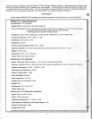
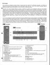
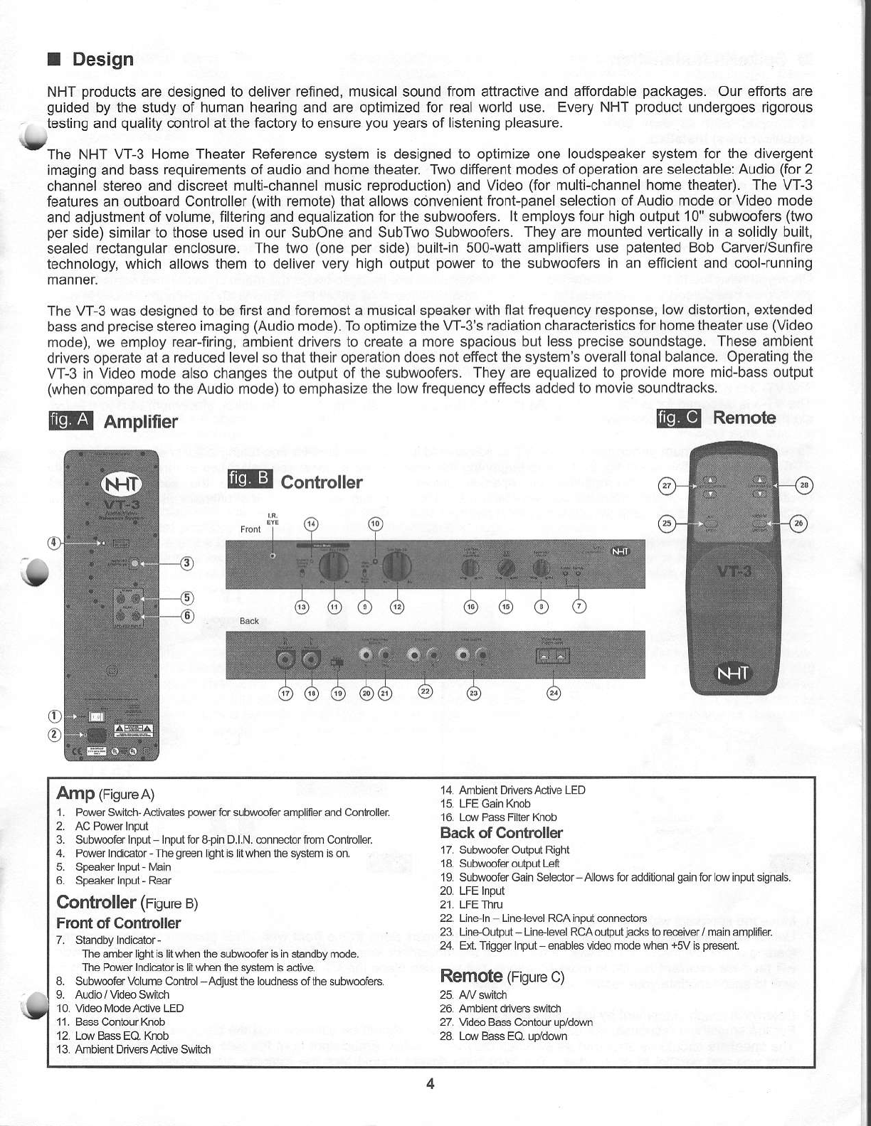
@
Amplifier ftp
Remote
@ Controller
Amp
(Figure
A)
1. PMr Switch Adi€ies
porer
tor subsefer amplifer and Conholls
3. SLbwfer npd InpLn id &pin D.l.N. dnedor i_om C.nto ler
4. PMr ndietor The
gEn
ight is lil when lt€ syslem is on.
6 Spe€ks npui
-
Re!.
Controller
(Figure
B)
Front of Confoller
The amber lighi is lil when t,le sLb$m€r is in slandby mode.
The P(rer Indlebr is lil when lhe s)stem
s adi!€.
8. Subr@fervoLumeCdlrol Adjci d1e loudll* of the
sub{e€6.
10. Vdeo ModeAcli€ LED
13. Ambient Ddve6 Adi@ Swiich
14. lnrbienl DivasAcllve
LED
15. LFE Gain Knob
16. LN Pass
FibrKnob
Back of Conboller
17. Subweler Oubul Righl
18. Sub@ier oLlpLn Lefl
19. SubwierGain Seledor A!l@s tor addi[onaLgain tor ]w inpLi sigmls.
20. LFE Inpd
21. LFEThT
22. Lneln L nelryel Rc,AinpdonneclDts
23. LnelLbd UelerelRcAoulpul
jacks
lo €ciwr/ ma n ampliner
24. Ext Tdgger inpLn ffibl6 vid@ mode un€n
+5V
is
p@nt
Remote
(Figure
c)
26. Ambient dn!€rs
swibh
27. Vrd6 Bas Conicur Lp/d@n
28 LorBass EO
uddown


