


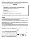
Installation: New Construction (unfinished walls)
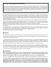
1. Begin by installing the mounting bracket between adjacent studs. The 6.2 Ci performs best
in the vertical orientation. The mounting bracket will not fit horizontally between studs with
16" centers. Attach the mounting wings to the bracket by inserting them into the locking plas-
tic tabs in the side of the bracket (fig.2).
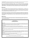
2. Select the desired location for the speaker, using a level to ensure that it is precisely
positioned. The wings feature progressively elongated sections (1", 1", 2", 2", 2", 3", 3") with
screw holes spaced in one-inch increments. Attach the wings to the studs with screws or
staples. Break off the extra portion of the wing by bending it at one of the pre-stamped
"break" lines (fig.3).
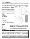
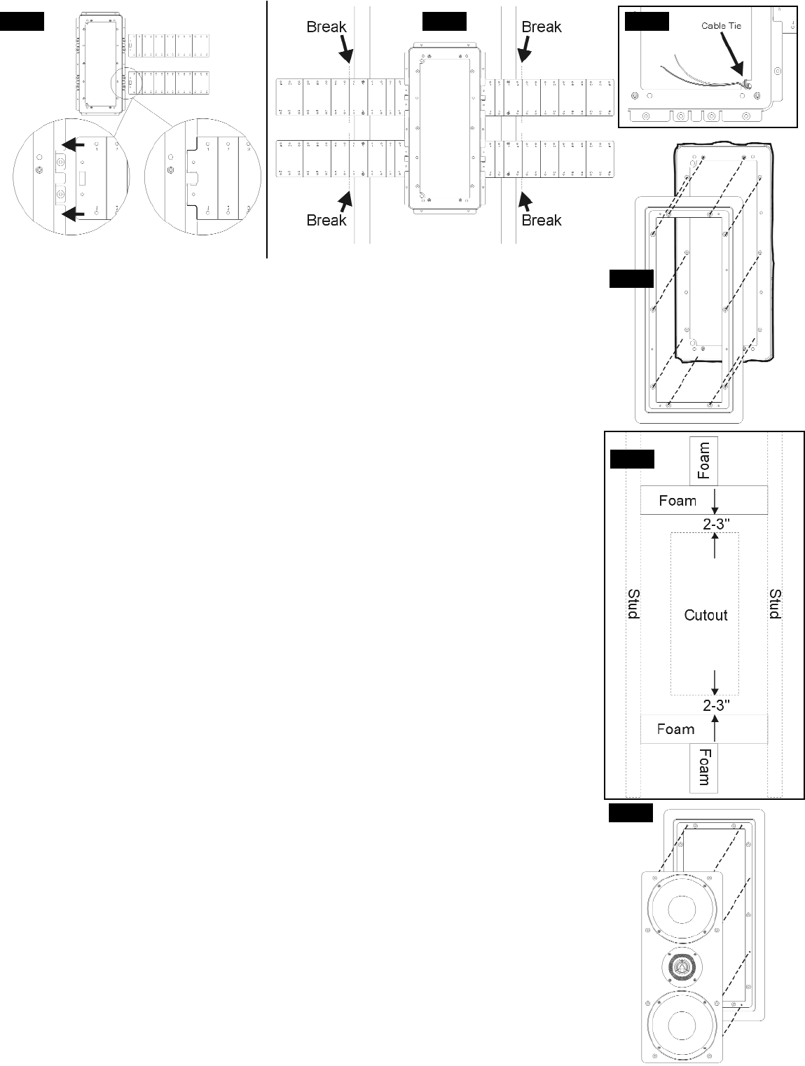
3. Complete the pre-wiring before the drywall goes up (see "Tech Tips: Pre-Wiring for New
Construction"). Leave an extra few feet of speaker cable, and secure it to the cable tie on the
mounting bracket (fig.4).
4. During the drywall phase, cut a hole 19-3/4" high by 8-7/8" wide around the bracket. The
bezel outer frame will extend out about 1 inch beyond the perimeter of the cutout to hide
minor imperfections in the cutout.
5. After the drywall is complete, attach the bezel to the bracket with ten 4 x XXmm flathead
screws that line up with the ten raised bosses on the bracket (fig.5). Tighten screws snugly,
making sure not to over-tighten, as this may compromise the fit of the bezel. The use of
power screwdrivers is not recommended. The absorptive strip on the back of the bezel's
outer frame reduces unwanted vibrations and will compress slightly to allow the frame to rest
flush against the wall on all four sides. When installed correctly, the bracket and bezel
"sandwich" the drywall.
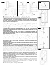
6. If the 6.2 Ci bezel frame and grille are to be painted in the wall, paint now before installing
the baffle (see "Painting").
7. Insert one of the 4" x 4" x 8" foam blocks vertically through the speaker cutout (fig. 6). Push
this block down approximately 7" below the edge of the cutout. Insert the second 4" x 4" x 8"
foam block and push up approximately 7" above the top edge of the speaker cutout. Bend
one of the 4" x 4" x 16" foam blocks into a U shape and push down into wall horizontally so
that it is 3" below the speaker cutout. Make sure that there is a good seal with the edge of
the foam and both the left and right wall studs. Repeat for the upper 4" x 4" x 16" foam block.
The foam should also make a good seal around the speaker wires. Add a 26" long piece of
unbacked R19 fiberglass insulation to the enclosure. (Be sure to wear protective gloves and
goggles when handling fiberglass to avoid contact with the fiber). You may need to cut a 7"
wide by 5" high rectangular hole in the center of the piece of fiberglass to make room for the
crossover on the back of the baffle.
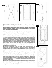
8. Connect the speaker cable to the spring posts on the 6.2 Ci baffle, making sure to observe
correct polarity (see "Connections").
9. Attach the baffle to the bezel with eight 4 x yymm screws that line up with the eight holes
in the bezel (fig.7). Exercise caution not to damage the drivers. Tighten screws snugly,
making sure not to over-tighten, as this may compromise the fit of the baffle. The use of
power screwdrivers is not recommended.
10. Attach the metal grille by inserting it into the bezel.
fig.5
fig.7
fig.6
fig.3fig.2 fig.4