


will flash for five seconds or press the Set
button to confirm the selection and the
display will return to the main menu. For
detail how to IR Sync the TX, see IR Sync
Programming in Programming sections of
HT-1KU and BT-1KU transmitter sections.
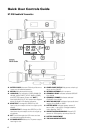
Adjusting the Squelch
In normal operation, each 8W-1KU receiver’s
Mute Control (16) works independently and
should be adjusted clockwise (CW) to the
minimum RF squelch setting at which
the RF Level Meter (12) and one of the LED
Diversity A/B Indicators (2) will remain on
while your transmitter is in normal use, up
to the maximum operating range anticipated
in use for your application. However, in
areas of high RF activity, the MUTE control
may need to be adjusted counterclockwise
(CCW). If the transmitter is off, the receiver
signal and the RF Signal Meter (12) and one
of the LED Diversity A/B Indicators (2) is
flickering or stay on continuously, the MUTE
level should be adjusted higher level CCW
(counterclockwise for less mute sensitivity
level) to stop the flickering. Be careful not
to adjust too high CCW setting as this may
reduce the operating range to below what
is needed. A range walk test will help in
selecting the proper level. If the range is
not critical, note that a counterclockwise
(maximum mute) setting will also yield
a quieter mute function, which might be
desired in certain applications. The MUTE
level is factory preset at clockwise (CW) for
maximum sensitivity and operating range
(i.e. clockwise (CW) for minimum squelch
level—maximum usable range).
Audio Level and Peak LED Indicator
The 8W-1KU receiver has an AF Peak LED (3)
display for each receiver and each works
independently per channel. The AF Peak
LED occasional flickering green on normal
or loud inputs to the transmitter is normal. If
the AF Peak LED lights green continuously,
you might overload the system. Decrease
the audio level input to the transmitter or
overload distortion sound may result.
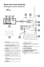
Connecting the Audio Outputs
8W-1KU receiver has one Unbalanced Audio
Out (17) (adjustable Line level) SUM audio
output and eight Balanced Mic Out (15) (fixed
level) XLR jacks and each output works
independently per receiver. The Unbalanced
Audio Out is controlled by
(Up) or
(Down) Buttons (7) for volume control and
the receiver Sum Volume Meter (11) will
indicate the level selected. For unbalanced
output, plug a ¼” mono (Tip/Sleeve) audio
cable into the Unbalanced Audio Out (17)
and plug the other end into your mixing
board or amplifier. When using the BT-1KU
instrument transmitter system, connect
the Unbalanced Audio Out directly to your
instrument amp or preamp. At maximum
receiver volume setting, as indicated by
the Sum Volume Level display, the system
output is approximately +4dB higher than
a direct cord-to-amp connection. Note that
all receivers output will be mixed together
as per the individual receivers’ volume
settings as selected by the up/down volume
controls. If separate signals are required for
each instrument then the Balanced Mic Out
sockets must be used. However, they are
not line level or adjustable. The SUM out is
best utilized for switching between separate
transmitters during performance with
only one audio signal at a time fed to the
instrument amplifier. For balanced output,
plug an audio cable with an XLR connector
into each receiver and plug the other end
into your mixing board or amplifier inputs
accordingly.
Note: As when making any connection, make sure
the amplifier or mixing board volume is at the
minimum level before plugging in the receiver to
avoid possible sound system damage.
10