


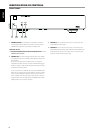
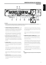


IDENTIFICATION OF CONTROLS
REAR PANEL
6 CHANNEL A SPEAKERS (applicable to CHANNEL A only): Connect the
right speaker to the CHANNEL A SPEAKERS terminals marked “R +” and “R-”
ensuring that the “R+” is connected to the “+” terminal on your loudspeaker
and the “R-” is connected to the loudspeaker’s “-” terminal. Connect the
terminals marked “L+” and “L-” to the left speaker in the same way.
In Bridge Mode, connect the single speaker to the terminals marked
“R +” and “L+” ensuring that the “L+” is connected to the “+” terminal
on your loudspeaker and the “R+” is connected to the loudspeaker’s “-”
terminal. Refer also to the section below about “BRIDGE MODE”.
Always use heavy duty (16 gauge; 1.5mm, or thicker) stranded wire to
connect loudspeakers to your NAD C 245BEE. The high-current binding
post terminals can be used as a screw terminal for cables terminating in
spade or pin sockets or for cables with bare wire ends.
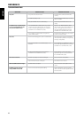
7 +12V TRIGGER IN/INPUT SENSE - OFF/AUTO: This dual function
switch alternates between sensing a +12V input as applied through the
+12V trigger IN jack or sensing any input signal applied at the CHANNEL
A IN or CHANNEL B IN sockets.
At AUTO setting and with the +12V trigger input of the C 245BEE
connected to the DC output jack of a compatible auxiliary component,
the C 245BEE can be switched remotely from standby mode to ON
and vice-versa. Use a 3.5mm mini-jack to pass +12V from the auxiliary
equipment into the C 245BEE.
If there is no 3.5mm mini-jack inserted at the +12V Trigger IN jack and
with the switch still at AUTO setting, the C 245BEE will instantaneously
turn ON from standby state if it senses any input signal (approximately
above 50mV RMS input) applied through CHANNEL A IN or CHANNEL
B IN sockets.
In the absence of a +12V trigger input or any input signal at CHANNEL
A IN or CHANNEL B IN sockets and with OFF/AUTO switch set to AUTO,
the C 245BEE will switch automatically to standby mode. Slide the OFF/
AUTO switch to OFF setting for the C 245BEE to be normally switched
ON (or back to standby mode) using the front panel STANDBY button.
IMPORTANT NOTICE
With the rear panel POWER switch at ON position and the OFF/AUTO
switch at AUTO setting, the C 245BEE cannot be switched ON using the
front panel STANDBY button. Slide the OFF/AUTO switch to OFF setting
for the C 245BEE to be normally switched ON (or back to standby mode)
using the front panel STANDBY button.
NOTES
• Switch the rear panel POWER switch to ON position in order to make use
of the +12V Trigger IN or Input Sense AUTO feature as well as the front
panel STANDBY button.
• It will take about 10 minutes for the C 245BEE to go to standby mode
when the input signal source is turned OFF.
8 +12V TRIGGER INPUT: The +12V Trigger input allows the C 245BEE
to be switched remotely from standby mode to ON and vice-versa
by ancillary equipments such as a preamplier, AV processor, etc. The
controlling device must be equipped with a 12V trigger output to
use this feature. Refer also to the section above about “+12V TRIGGER
IN/INPUT SENSE - OFF/AUTO”.
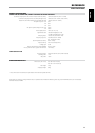
9 FUSE HOLDER: In the unlikely event a fuse may need to be replaced,
unplug the AC cord from the wall. Then, remove all connections from
the amplier. Use a athead screw driver or similar to open the fuse
holder via the slot indicated. With the screw driver in place, push and
turn counterclockwise to open the fuse holder. Only replace the fuse
with the same type, size, and specication – T3.15AL 250V for 230V
version or T6.3AL 250V for 120V version.
IMPORTANT NOTICE
Do not use any substitute fuses of dierent types or with dierent ratings
or values. Failure to observe this precaution may cause damage to the
amplier circuits and may create a re hazard and/or defeat the safety
built into the amplier and may void the warranty.
10 AC MAINS INPUT: The C 245BEE comes supplied with a separate AC
Mains cable. Before connecting the cable to a live wall socket ensure
that it is rmly connected to the C 245BEE’s AC Mains input socket rst.
i.e., 120V 60 Hz (for 120V version models of C 245BEE only) or 230V 50
Hz (for 230V version models of C 245BEE only). Always disconnect the
AC Mains cable plug from the live wall socket rst, before disconnecting
the cable from the C 245BEE’s Mains input socket.
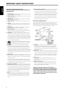
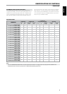
11 POWER SWITCH: The POWER switch supplies the master AC mains
power for the C 245BEE. Refer to the ATO LOGIC chart below for a better
understanding of the role of the POWER switch when switching ON
or OFF the C 245BEE. If you intend not to use the C 245BEE for long
periods of time (such as when on vacation), switch OFF the POWER
switch.
8
ENGLISH FRANÇAIS ESPAÑOL ITALIANO DEUTSCH NEDERLANDS SVENSKA РУССКИЙ