


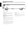
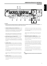


1 CHANNEL B SPEAKERS (applicable to CHANNEL B only): Connect the
right speaker to the CHANNEL B SPEAKERS terminals marked “R +” and “R-”
ensuring that the “R+” is connected to the “+” terminal on your loudspeaker
and the “R-” is connected to the loudspeaker’s “-” terminal. Connect the
terminals marked “L+” and “L-” to the left speaker in the same way.
In Bridge Mode, connect the single speaker to the terminals marked “R +”
and “L+” ensuring that the “L+” is connected to the “+” terminal on your
loudspeaker and the “R+” is connected to the loudspeaker’s “-” terminal.
2 BRIDGE MODE (applicable to CHANNEL B only): Set the BRIDGE
MODE switch to the “ON” position and connect the speaker to the
terminals marked “L +” and “R+” ensuring that the “L+” is connected to
the “+” terminal of your loudspeaker and the “R+” is connected to the
loudspeaker’s “ - ” terminal. Connect the input source to the CHANNEL
B IN sockets.
3 CHANNEL B (IN/OUT): Connect the output from a pre-amplier or
processor, such as a surround-sound decoder, to this set of CHANNEL
B IN sockets. Use a twin RCA-to-RCA lead to connect the left and right
“Audio Output” of the preamplier or processor to these CHANNEL B
input sockets.
CHANNEL B OUT is line level “loop through” output. The same level of
input signal at the CHANNEL B IN sockets is available at CHANNEL B
OUT sockets thereby allowing the same signal to be shared or passed
on to another amplier.
Always turn OFF the C 245BEE and other components in the system
before connecting or disconnecting anything to the CHANNEL B IN
sockets.
4 CHANNEL A (IN/OUT): Connect the output from a pre-amplier or
processor, such as a surround-sound decoder, to this set of CHANNEL
A IN sockets. Use a twin RCA-to-RCA lead to connect the left and right
“Audio Output” of the preamplier or processor to these CHANNEL A
input sockets.
CHANNEL A OUT is a line level “loop through” output. The same level
of input signal at the CHANNEL A IN sockets is available at CHANNEL A
OUT sockets thereby allowing the same signal to be shared or passed
on to another amplier.
Always turn OFF the C 245BEE and other components in the system
before connecting or disconnecting anything to the CHANNEL A IN
sockets.
5 BRIDGE MODE (applicable to CHANNEL A only): The C 245BEE
amplier can be congured to be MONO (Bridge Mode), more than
doubling its output power. This way, the C 245BEE can be used as
part of a high power stereo or home-theatre system, by connecting
additional power ampliers.
In BRIDGED MODE, the C 245BEE will produce approximately 70W into
an 8 ohm loudspeaker. In this mode, the amplier sections will react
as though the speaker impedance has been halved. Low impedance
speakers (under 8 ohms) are not recommended when using Bridge
Mode as these may cause the amplier’s thermal cut-out to operate if
played at high levels.
Set the BRIDGE MODE switch to the “ON” position and connect the
speaker to the terminals marked “L +” and “R+” ensuring that the “L+”
is connected to the “+” terminal of your loudspeaker and the “R+” is
connected to the loudspeaker’s “ - ” terminal. Connect the input source
to the CHANNEL A IN sockets.
NOTE
Do not connect anything to the Right Input socket when Bridge Mode is
selected.
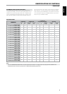
IDENTIFICATION OF CONTROLS
REAR PANEL
1 2 5 6 7 8 9
3 4
ATTENTION!
Please make sure that the C 245BEE is powered OFF or unplugged before making any connections. It is also advisable to power-down or unplug all
associated components while making or breaking any signal or AC power connections.
1110
7
ENGLISHFRANÇAISESPAÑOLITALIANODEUTSCHNEDERLANDSSVENSKAРУССКИЙ