


15
Installation, con’t
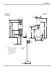
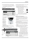
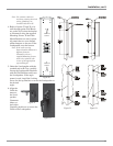
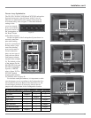
Remove
Screws
Remove
Screws
Figure 20
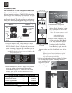
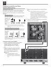
Note: Use extreme caution to
avoid any existing electrical
wiring, plumbing, etc.,
located inside the wall.
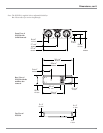
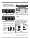
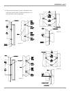
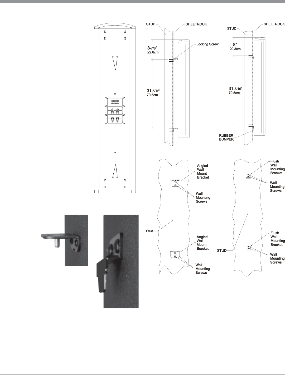
4. Refer to figures 23 and 24 to in-
stall the appropriate Wall Brack-
ets on the wall (orient the bracket
as illustrated) using the supplied
Mounting Screws. If the Flush
Mount Brackets are used, option-
ally attach the two cone shaped
rubber bumpers to the rear of the
Loudspeaker, near the bottom.
Note: If the wall covering
material and/or thickness is
different from the
illustration, the two
supplied Mounting Screws
need to be replaced with
screws of the appropriate
type and length.
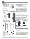
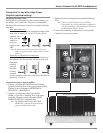
5. Orient the Loudspeaker with the
rounded end at the Top, carefully
line up the Loudspeaker Brackets
with the Wall Brackets and lower
the Loudspeaker. If the angle
mount is used, install the Locking
Screw for the top Bracket to secure the Loudspeaker at
the desired
angle.
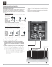
6. Align the
Grille fas-
teners to
the Loud-
speaker
Grommets
(three on
each side).
Carefully push down to secure the
Grille to the Loudspeaker.
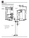
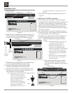
Figure 21
Figure 22
Figure 23 Figure 24