


7
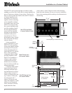
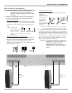
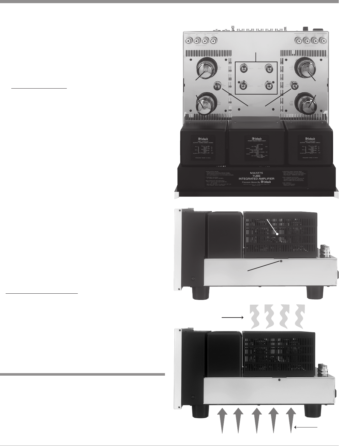
Warm Air
Cool Air
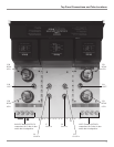
Installation of Tubes, Tube Cover, Location and Ventilation
6. Repeat the above the steps for the remaining 3 Power
Output Tubes.
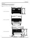
There are two different types of Small Signal Tubes
(12AX7A and 12AT7) used in each channel. Tube type can
be found on the outside of the Tube. The MA2275 will not
function if they are inserted into the wrong socket.
Small Signal Tubes:
1. Locate a 12AX7A Tube.
2. On the top center area of the amplifier, locate the
Tube Socket that has the nomenclature V4 12AX7A
next to it on the chassis. Refer to figure 4.
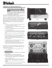
3. Orient the Tube so the area where no pins are located
on the base of the Tube is aligned with the corre-
sponding area on the Tube Socket.
4. Carefully insert the Tube into the socket until the base
of the Tube is fully seated in the Tube Socket.
5. Repeat the above steps for the remaining three
12AX7A Tubes. Refer to figure 5.
6. Locate a 12AT7 Tube.
7. On the right side of the amplifier, locate the Tube
Socket that has the nomenclature V1R 12AT7 next to
it on the chassis. Refer to figure 4.
8. Insert the Tube, following the same procedure as in
steps 3 and 4.
9. Repeat steps 6-9 for the remaining 12AT7 Tube. Re-
fer to figure 5.
Caution: To prevent electrical shock make sure the MA2275
Tube Cover is installed before connecting the AC
Power Cord.
Before operating the MA2275, locate the previously re-
moved Tube Cover and perform the following steps:
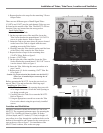
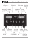
Installing the Tube Cover:
1. The Tube Cover has a wide opening along one side
of its longer dimension. Orient this wide opening so
it is facing towards you.
2. Carefully place the Tube Cover onto the MA2275.
Refer to figure 6.
3. Using an appropriate screwdriver secure the Tube
Cover to the chassis using the previously installed
screws.
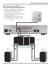
Adequate ventilation extends the trouble free life of the
MA2275. The suggested minimum space for operating the
MA2275 is 24 inches (60.96cm) in width, 20 inches
(50.8cm) depth, and 22.5 inches (57.15cm) in height. Al-
ways allow air to flow through the ventilation holes on the
bottom of the amplifier and a means for the warm air to es-
cape at the top, refer to figure 7. For installation of the
MA2275 into a cabinet, refer to the next page.
Location and Ventilation
Figure 7
Figure 5
Tube Cover Fastening Screw Locations
Tube Cover
Figure 6
Tube Cover
Fastening
Screw
Location
12AX7A
12AT7
KT88/
6550
KT88/
6550