


6
Installation of Tubes and Tube Cover
Caution: To prevent electrical shock make sure the AC
POWER CORD IS NOT CONNECTED TO THE
MA2275 . Also do not touch the Vacuum Tube
Connection Pins when inserting or removing them,
as there may be hazardous voltages present at the
Tube Socket Pins even after the MA2275 has been
switched Off for a period of time.
Your MA2275 has gone through an extensive series of per-
formance tests during the manufacturing process. The
MA2275 is supplied with the actual Tubes that were used
to test and confirm the performance of this integrated am-
plifier. To protect the Vacuum Tubes from possible ship-
ping damage, they are packed in five layers of foam,
placed into the Tube Cover and secured to the MA2275
Chassis.
Note: Gloves or a soft cloth will prevent “fingerprinting” of
the Tubes during their installation.
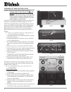
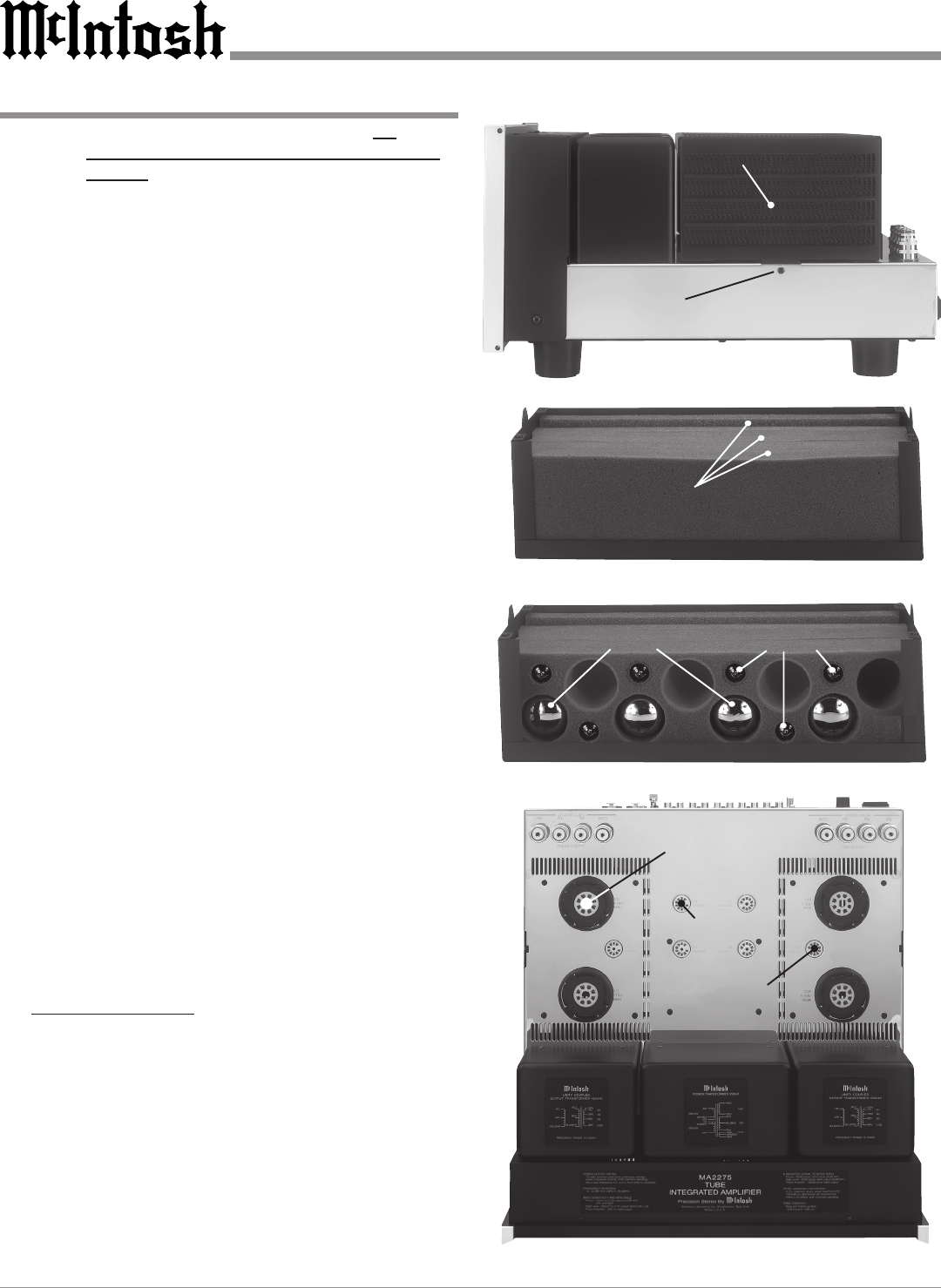
1. Orient the MA2275 so the right Side Panel is facing
you. Refer to figure 1.
2. Using an appropriate screwdriver, remove the Tube
Cover Fastening Screw.
3. In a similar manner, remove the Tube Cover Fasten-
ing Screw from the left side of the integrated ampli-
fier.
4. Remove the tube cover from the MA2275 Chassis.
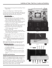
5. Orient the Tube Cover to the wide opening along one
side of its longer dimension. Refer to figure 2.
6. Remove the first layer of foam to expose the Tubes.
Refer to figure 3.
7. Carefully remove the Tubes from the foam and tem-
porarily place them in a safe location.
8. Remove the remaining foam from the Tube Cover
and retain all five pieces for possible future use.
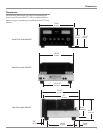
The MA2275 Chassis has nomenclature screened on it to
specify the location in the circuit and Tube Type for each
channel. Refer to figure 4.
Note: It is extremely important to insert the Tubes in the
correct location.
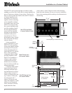
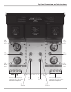
Power Output Tubes:
1. Orient the Chassis so the Front Panel of the Amplifier
is facing you.
2. Locate a KT88 or 6550 Power Output Tube.
3. On the top left side of the amplifier, locate the Tube
Socket that has the nomenclature V3L KT88/6550
next to it on the chassis.
4. Orient the Tube so the key on the base of the Tube is
aligned with the corresponding key on the Tube
Socket.
5. Carefully insert the Tube into the socket until the base
of the Tube is fully seated in the Tube Socket.
Figure 1
Tube Cover
Fastening
Screw
Location
Figure 2
Tube Cover with
Layers of Foam
and Tubes
Figure 3
Power Output Tubes
Small Signal Tubes
Figure 4
V3L - KT88/6550 Tube
V1R - 12AT7 Tube
V4 - 12AX7A Tube