19
Technical Description, con’t
tronic attenuator at the amplifier input reduces the input
volume just enough to prevent any further increase in dis-
tortion. The Power Guard circuit acts so fast that there are
absolutely no audible side effects and the sonic purity of
the music reproduction is perfectly preserved. The MC252
Power Amplifier with Power Guard is not limited to just
the rated power output, but will actually produce distortion
free output well above its rated power due to the McIntosh
philosophy of conservative design.
Power Supply Circuits
To compliment the design of the MC252, there is a high
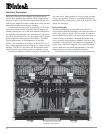
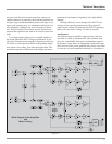
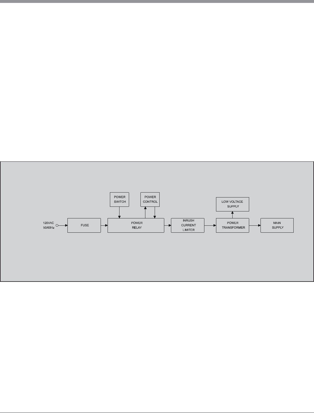
voltage power supply for both channels. Refer to figure 20.
The power amplifiers draw high current from the AC
power line. Therefore, it is important that they plug directly
into the wall outlet.
Also, most owners desire that there be one power
switch for the whole audio system. The MC252 is equipped
with a circuit that provides remote Power Control from
Figure 20
Block Diagram
of the
Power Supply
your McIntosh Preamplifier or Control Center. When you
turn on your preamplifier a digital “1” (+5V) signal oper-
ates the power relay in the MC252. The MC252 also has a
remote Power Control Out Jack. The Power Control signal
from this jack is delayed by a fraction of a second so that
the turn on power surge of the next power amplifier occurs
at a later time. This helps prevent power circuit overload
that could trip circuit breakers or blow fuses, a very impor-
tant feature in a high power Home Theater System employ-
ing three MC252 Power Amplifiers.
The MC252 can provide greater than 50 amperes peak
output current to drive uneven speaker loads. Some poor
speaker designs have input impedance that dip to 1 or 2
ohms at various frequencies and the MC252 has the output
current reserve to drive them. The MC252 has main filter
capacitors that guarantee an excellent signal to noise ratio
and the energy storage necessary for the wide dynamic
range that “Digital Audio” demands.


